- 3 -
10. Front channel High-Pass frequency selector.
11. Rear channel High-Pass frequency selector.
12. Frequency Multiplier:
for Front Channel High Pass Frequency selector.
13 & 14: Front and Rear Channel Slope Selectors:
Move the selector switch to the 6 dB
position when little or no attenuation as well as little or no separation is required between the
selected frequency and the next adjacent frequency. Selected 12dB position when greater
definition and/or attenuation is desired between the selected frequency and the other
adjacent frequencies.
15. Subwoofer Low Pass Frequency Selector.
16. Bass Boost Level Control.
17. Bass Boost Frequency Selector.
18. Phase Shift Selector switch:
Use this switch to select output phase for the subwoofer
channel to provide best time alignment and stereo imaging.
19. Stereo / Mono Switch:
For selection of stereo and mono mode for subwoofer output
signal.
20 & 22. Front and Rear Channel High Pass Level Controls.
21. Front Channel Outputs Terminals.
23. Rear Channel Outputs Terminals.
24. Subwoofer Low Pass Level Control
25. Subwoofer Channel Outputs Terminals.
26. Subwoofer Remote Level Control Jack:
To be connected to the remote control for
adjusting the output level of subwoofer output.
(Note: The remote control will adjust to the
highest preset setting of the subwoofer low pass level control.)
27. Fuse:
Use only a 3 AMP fuse for replacement.
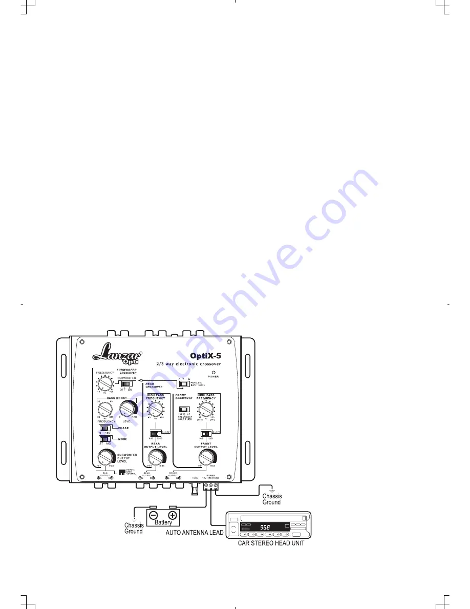
WIRING DIAGRAM : Power Connection
Summary of Contents for Optidrive OPTIX-5
Page 1: ......
Page 5: ...4 SIGNAL CONNECTION SYSTEMS...
Page 6: ...5...
Page 8: ...www lanzar com...


