background image

Lantronix


            SDSTX3110-124-LRT-B User Guide 

33686 Rev. C 

https://www.lantronix.com/


86 

Certifications 

Safety: UL508, TUV EN60950-1, NEC Class 2/LPS 

EMC Emissions: EN55011, EN55022, CISPR22, 

EN61204-3 Class B, EN61000-3-2, EN61000-3-3 

EMC Immunity: EN61000-4-2, EN61000-4-3, 

EN61000-4-4, EN61000-4-5, EN61000-4-6, 

EN61000-4-8, EN61000-4-11, EN55024, 

EN61000-6-1, EN61204-3 A 

IEC60068-2-6 (Vibration) 
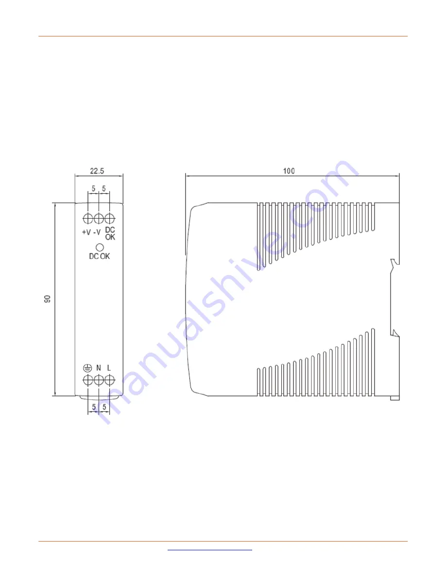
 

25135 Dimensions 


Summary of Contents for SDSTX3110-124-LRT-B

Page 1: ...SDSTX3110 124 LRT B Industrial Serial Device Servers User Guide Part Number 33686 Revision C March 2022 ...

Page 2: ...ffices go to www lantronix com about contact Disclaimer All information contained herein is provided AS IS Lantronix undertakes no obligation to update the information in this publication Lantronix does not make and specifically disclaims all warranties of any kind express implied or otherwise regarding title non infringement fitness quality accuracy completeness usefulness suitability or performa...

Page 3: ...nel 12 3 Hardware Installation 12 3 1 DIN Rail Installation 12 3 2 Wall Mounting 14 3 3 Rack Mounting 15 3 4 Wiring 16 3 4 1 Grounding 16 3 4 2 Redundant Power Inputs 16 3 5 Connection 17 3 5 1 10 100BASE T X Pin Assignments 17 3 5 2 Cable Types and Specifications 17 4 Management 18 4 1 SDS Manager 18 4 1 1 Install the SDS Manager 18 4 1 2 SDS Manager Overview 20 4 1 3 Using SDS Manager 21 File 21...

Page 4: ...onsole 68 4 6 Uninstall SDS Manager 80 5 Technical Specifications 82 Power Supply Specifications 83 25130 Features and Specifications 83 25135 Features and Specifications 85 6 Troubleshooting 87 6 1 FAQs 87 6 2 Procedure 88 6 3 Record Model and System Information 89 6 4 Package and Device Labeling 90 7 Safety and Compliance Information 91 7 1 Compliance Information 91 FCC Regulations 91 Canadian I...

Page 5: ...ly 25130 Industrial DIN Rail Mounted Power Supply Input 85 264 VAC 120 370 VDC Output 48VDC 0 83A 39 8 Watts 25135 Industrial DIN Rail Mounted Power Supply Input 85 264 VAC 120 370 VDC Output 24VDC 0 42A 10 Watts 1 2 Features Operating Modes Virtual Com Serial Tunnel TCP Server TCP Client UDP Redundant multiple host devices o 5 host devices Virtual COM TCP Server TCP Client mode o 4 IP ranges in U...

Page 6: ...de 33686 Rev C https www lantronix com 6 1 3 Applications The figures below show typical SDS configurations e g Multiple Host PCs SSL Data Encryption TCP Client Server Modes and NAT Router Pass through Multiple Host PCs SSL Data Encryption ...

Page 7: ...Lantronix SDSTX3110 124 LRT B User Guide 33686 Rev C https www lantronix com 7 TCP Client Server Modes NAT Router Pass through ...

Page 8: ...LRT B User Guide 33686 Rev C https www lantronix com 8 1 4 Dimensions 1 4 1 SDSTX3110 124 LRT B Dimensions The SDSTX3110 124 LRT B cabinet dimensions are provided below 66 W x 81 D x 95 H mm 2 5 8 W x 3 1 4 D x 3 3 4 H inches ...

Page 9: ...location Save the packing materials for possible future use Verify that you received the items below Contact your sales representative if you have not received all the following items One SDSTX3110 12x LRT B Two wall mounted brackets or two DIN rail brackets One 5 5x2 0 DC Jack to 1 pair Cable 200mm Black Female D2C 2001 One support Postcard One Accessory Kit with one Plastic Bag containing one 4 ...

Page 10: ...e Ethernet ports on the device use RJ45 connectors Port Description Copper Ports 1 and 2 Two 10 100 Base T X ports ETH 10 100M Serial Ports S1 S4 Four DB9 Serial Ports SDSTX3110 124 LRT B Reset button Press the front panel Reset button to re load all of the factory default settings Hardware reset 2 1 2 Front Panel SDSTX3110 124 LRT B Front Panel ...

Page 11: ...this LED Tx Green On Transmitting serial data on the port below this LED LOCATE Green On The front panel LOCATE LED can help you identify the intended SDS device The LOCATE LED lights when activated The LOCATE LED stays on until deactivated To locate a specific SDS among many devices in a data center use the SDS Manager to light the SDS front panel LOCATE LED 2 2 Top Panel Below are the top panel ...

Page 12: ...w are the back panel components with the pre installed DIN rail kit removed Below is the back panel shown with the pre installed DIN rail kit 3 Hardware Installation 3 1 DIN Rail Installation A DIN Rail kit is pre installed to let you fasten the device to a DIN rail The dimensions are provided below ...

Page 13: ...Lantronix SDSTX3110 124 LRT B User Guide 33686 Rev C https www lantronix com 13 SDSTX3110 124 LRT B Dimensions in mm ...

Page 14: ...The SDS can be fixed to the wall via the wall mount kit included in the package The wall mount kit dimensions are provided below To install the device on a panel or wall 1 Remove the Din Rail clip by removing the three screws 2 Use the screws included in the package to install the wall mount bracket ...

Page 15: ...ounting The SDS can be rack mounted using the procedure below 1 Install the provided L shaped mounting brackets to the left and right sides of the device as shown below 2 With the front brackets oriented in the front of the rack mount the device in the rack with the four rack mounting screws ...

Page 16: ...ting devices 3 4 2 Redundant Power Inputs The device has two sets of DC power inputs on the 4 pin terminal block located on top of the device Follow the steps below to wire the power input on the terminal block 1 Insert the Terminal Block connector into the keyed receptacle on the SDS 2 Insert the negative positive wires into the V and V terminals respectively 3 To keep the wires from pulling loos...

Page 17: ...ble below for cable specifications With 10 100BASE T X cables pins 1 and 2 are used for transmitting data and pins 3 and 6 are used for receiving data Note that the and signs represent the polarity of the wires that make up each pair Pin Number Assignment 1 TD 2 TD 3 RD 4 Not used 5 Not used 6 RD 7 Not used 8 Not used 3 5 2 Cable Types and Specifications Cable Type Max Length Connector 10BASE T CA...

Page 18: ...indows systems 1 Determine which version you require 2 Download it from the Lantronix website SDS Management Software zip file e g filename SDS Manager_x64_v1 5a_20160413 zip 3 Unzip the Zip file e g SDS Manager_x64_v1 5a_20160413 exe 4 Note the name and location of the executable file s Firmware file name is SDSTX3110 124 LRT B_20161221_1 4_uImage SDS Manager file names are SDS Manager_x64_v1 5a ...

Page 19: ...her the Launch SDS Manager Now checkbox or the Launch SDS Manager Later checkbox When you launch SDS Manager a confirmation message displays 5 Click Yes to restart your computer to complete the installation or select No and restart it later The SDS Manager startup screen Device List displays ...

Page 20: ...e Load Apply and Save Apply all changes and save to Flash Load Default Load factory default settings except for the IP address Reboot Device Import Export Configuration Save the configuration of device as a file Import the pre saved configuration file to apply to new device 4 Go to the port menu and configure the port settings Serial Settings Configure the Port alias baud rate parity data bits sto...

Page 21: ... Done File Serial Tunnel Wizard helps you couple two serial devices to directly communicate by Ethernet without the PC STEP 1 Select two devices that should be tunneled together STEP 2 Select serial parameters such as baud rate data bits STEP 3 Finish File Group IP Wizard helps you configure the IP addresses of a group of new devices The devices already in the configuration list will not be includ...

Page 22: ... Add Device by IP lets you search by Domain Name IP Range and or Management Port Number or lets you cancel the search Device Configuration Remove Device lets you remove a selected device from the configuration Device Configuration Import Device Configuration lets you import a selected device into the configuration Device Configuration Export Device Configuration lets you export a selected device o...

Page 23: ...ion Broadcast Search menu path SDS Manager will broadcast to the network and search for all available SDS devices on the network automatically The default IP address of the device is 192 168 1 77 Select the device you want to use and press the Add button You can set a static IP address or use the DHCP client mode to acquire an IP address automatically Click OK and the device will be added ...

Page 24: ...domain name or IP address and the port number then select a time zone SNTP Server IP Displays the current SNTP Server IP address Port Displays the currently configured port number e g port 123 Time Zone Displays the currently configured Time Zone e g ADT Atlantic Daylight UTC minus 3 hours Auto IP Report Check the checkbox to receive IP reports regularly By clicking Get Current Host you will get y...

Page 25: ...Label Description Access IP Table You can enter the host IP addresses and network masks to prevent unauthorized access Check the Enabled checkbox to enable each IP address for access Password You can set or change the password to prevent unauthorized access from your server The factory default is no password empty field Click the Change Password button when done User Name Enter the new User Name C...

Page 26: ...es Static IP or DHCP BOOTP The factory default IP address is 192 168 1 77 Wire Sub Tab Label Description Using Static IP Manually assign an IP address to the device Using DHCP BOOTP Check the box to have the IP address automatically assigned by a DHCP server in your network IP Address Enter the IP address of the serial device server Netmask All devices on the network must have the same network mas...

Page 27: ...box is checked Email Notification Check the box to allow the system to send emails when an event occurs You must specify the SMTP Server and the email address to use for sending emails if the box is checked Syslog Notification Check the box to allow the system to send a detailed log to an external Syslog server when an event occurs The syslog will capture all log activity and includes every connec...

Page 28: ...ipment is powered off A notification will be sent if the box is checked RI Changed When the RI Ring Indicator signal changes it indicates the incoming of a call A notification will be sent if the box is checked CTS Changed When the CTS Clear To Send signal changes it indicates that the transmission between computer and DCE can proceed A notification will be sent if the box is checked Port Connecte...

Page 29: ...ment from the web Click the Goto Web Management button to access the web Telnet Management Enable Check the box to enable management by Telnet Click the Goto Telnet Management button to execute Telnet commands SNMP Management Enable Check the box to enable management by SNMP SNMP Management Settings If SNMP Management Enable is checked you must fill in the SNMP settings in these fields by assignin...

Page 30: ...he Upgrade button to start the upgrade process Label Description Firmware Image Provide the path and filename The firmware image is typically a bin file or a uImage file Browsing Click the button to browse to and select the desired firmware image file Upgrade Click the button to upgrade the SDS device to the selected firmware image file Refresh Click the button to update the screen content undo ch...

Page 31: ...lick this button to re boot the device you must broadcast again to search for the device warm start Import Configuration Click this button to retrieve a saved configuration file and apply it to the current device Export Configuration Click this button to save the current parameters to a file and export it to a current host At the Save As dialog browse to a Save in location enter a file name and fi...

Page 32: ... configure the settings for each serial port by clicking on the port number in the left pane of the window When you click on a port in the left pane the screen below displays in the right panel This page displays the Serial Settings Service Mode and Notification tabs as described and shown in the following sections ...

Page 33: ... simple form of error detection which guards data on the cable between the connected devices and the serial port The available Parity options include None no parity checking is performed and the parity bit is not transmitted Odd the number of mark bits in the data is counted and the parity bit is asserted or unasserted to obtain an odd number of mark bits Even the number of mark bits in the data i...

Page 34: ...nclude RS 232 RS 422 RS 485 2 wires and RS 485 4 wires After a Virtual COM has been mapped to a port changes to the serial settings of that port e g from RS232 to RS422 should not be made Performance Throughput guarantees highest transmission speed Latency guarantees shortest response time Delimiter Settings Serial to Ethernet Ethernet to Serial For advanced data packing options you can specify de...

Page 35: ... Port number Control Port Displays the control port number read only Map Virtual COM Click to select a Virtual COM name to map on Idle Timeout When a serial port stops data transmission for a defined period of time Idle Timeout the connection will be closed and the port will be freed and try to connect with other hosts 0 means the function is disabled which is also the factory default value If mul...

Page 36: ...s can be supported simultaneously is 5 default value is 1 Destination Host Displays one to four connected destination hosts VCOM Name Displays the related VCOM name or a message like Waiting for VCOM connect Goto VCOM Click the button to go to the related VCOM port Unmap VCOM Click the button to un map the related VCOM port ...

Page 37: ...rver to help provide an enhanced user experience Data Port Set the port number for data transmission Auto Scan Click to scan the data port automatically Idle Timeout When a serial port stops data transmission for a defined period of time Idle Timeout the connection will be closed and the port will be freed and try to connect with other hosts 0 means the function is disabled which is also the facto...

Page 38: ... C https www lantronix com 38 Max Connections Up to 5 connections can be supported simultaneously the default value is 1 Destination Host Input the IP address of one to five destination hosts Disconnect Click to disconnect a connected destination host ...

Page 39: ...defined period of time Idle Timeout the connection will be closed and the port will be freed and try to connect with other hosts 0 means the function is disabled which is the factory default value If multilink is configured only the first host connection is effective for this setting Alive Check The serial device will send a TCP alive check package in each defined time interval Alive Check to remo...

Page 40: ...e 33686 Rev C https www lantronix com 40 Auto Scan Click the button to scan for the listening port number of the device Multilink Destination Host Enter the Multilink Destination Host IP address Multilink Port Enter the Multilink Port number ...

Page 41: ...stination Host Begin End If there are more than one destination hosts specify the IP address range by inputting a value in destination host IP begin end fields You can also auto scan the sending port number of the device Sending Port IP port for sending outgoing messages Messages Message Apply or Discard The settings has been changed Apply to device or discard Meaning You made changes and then lef...

Page 42: ... www lantronix com 42 Message Warning UDP mode s Port is in used on Device Meaning You tried to configure the same UDP Listening or UDP Sending port number for two instances Recovery 1 Click the OK button to clear the Warning dialog 2 Change a UDP port number ...

Page 43: ... Items The VCOM List COMx Serial Settings tab displays Link Information and current serial device settings Baudrate Stop Bits Parity Flow Control Data Bits and Interface selections The VCOM List COMx Connection Settings tab displays Link Information and current serial settings Remote Device IP Port and Connection Status The VCOM List COMx Statistics tab displays Link Information and current Statis...

Page 44: ...zard Group IP Wizard Group Setup Wizard and Group Firmware Wizard 4 2 8 IP Collection The IP Collection page displays automatically collected IP address device name model last report of devices by a defined time interval 4 2 9 System Log The System log page displays current log messages of the device lets you clear the messages and lets you display messages based on a Year and Month selection ...

Page 45: ...nch a Web browser 2 Type the IP address of the device and press Enter A login screen displays 3 Type the default username root Type the default password root You may set up a different user name and password later on the IP Configuration page 4 Press Enter or click OK the System Information page displays Note you can use the following default values IP address 192 168 1 77 Subnet Mask 255 255 255 ...

Page 46: ...with a server that has already been synchronized by a source such as a radio satellite receiver or modem Label Description Name Enter the model name of the device SNTP Enable or disable SNTP function Time Zone Choose the time zone according to the location of the device Local Time Set up the local time Time Server Enter the address of the time server Telnet Console Click to enable or disable Telne...

Page 47: ...ard ADT Alaskan Daylight 8 hours 4 am ALA Alaskan Standard 9 hours 3 am HAW Hawaiian Standard 10 hours 2 am Nome Alaska 11 hours 1 am CET Central European FWT French Winter MET Middle European MEWT Middle European Winter SWT Swedish Winter 1 hours 1 pm EET Eastern European USSR Zone 1 2 hours 2 pm BT Baghdad USSR Zone 2 3 hours 3 pm ZP4 USSR Zone 3 4 hours 4 pm ZP5 USSR Zone 4 5 hours 5 pm ZP6 USS...

Page 48: ...HCP the following fields will gray out Static Enter an IP address for the device Select Static IP if you are using a fixed IP address DHCP BOOTP allows the IP address of the device to be automatically assigned by a configuration server IP Address Enter the IP address that identifies the server on the TCP IP network The default is 192 168 10 1 Netmask Enter a subnet mask for the device The default ...

Page 49: ...hange your password Label Description User Name Enter the default User Name root in lower case Old Password Enter the existing password that is used to log in New Password Enter a new password that will be used to log in Confirm New Password Retype the new password to confirm Click the Apply button when done to apply the changes ...

Page 50: ...7 or 8 Data is transmitted as a series of seven or eight bits five and six bit data formats are used rarely for specialized communications equipment Stop Bits Choose the number of bits used to indicate the end of a byte You can configure stop bits to be 1 or 2 1 5 If Stop Bits is 1 5 the stop bit is transferred for 150 of the normal time used to transfer one bit Both the computer and the periphera...

Page 51: ...ide will send an XON character over its Tx line to tell the transmitting side to resume transmitting In hardware flow control mode when the device is ready to receive data it sends a CTS Clear To Send signal to the device on the other end When a device has something it wants to send it will send a RTS Ready To Send signal and waits for a CTS signal to come back its way These signals are sent apart...

Page 52: ...to Ethernet or Ethernet to Serial read only Flush Data Buffer After The received data will be queuing in the buffer until all the delimiters are matched When the buffer is full 4K Bytes or after flush S2E data buffer timeout the data will also be sent You can set the time from 0 to 65535 milliseconds ms Delimiter Hex 00 ff For advanced data packing options you can specify delimiters for Serial to ...

Page 53: ... device server is assigned a unique port number TCP Client Mode the device can establish a TCP connection with the server by the method you set Startup or any character After the data has been transferred the device can disconnect automatically from the server by using the TCP alive check time or idle timeout settings UDP Mode In UDP mode you can uni cast or multi cast data from the serial device ...

Page 54: ...P Server Port Enter the TCP server port The default is port 4000 Idle Timeout When serial port stops data transmission for a defined period of time the connection will be closed and the port will be freed and try to connect with other hosts 0 indicate disable this function The factory default value is 0 If Multilink is configured only the first host connection is effective for this setting Alive C...

Page 55: ...d period of time the connection will be closed and the port will be freed and try to connect with other hosts 0 indicate disable this function Factory default value is 0 If Multilink is configured only the first host connection is effective for this setting Alive Check The serial device will send TCP alive check packages in each defined time interval to remote host to check the TCP connection If t...

Page 56: ...bel Description Listen Port Allows the user to set a new TCP port number to listen on rather than the default value of the device The default is port 4000 Host Start IP Host End IP If there are more than one destination hosts specify the IP address range by inputting a value in Host Start End IP You can also auto scan the sending port number of the device The valid range for both is 1 0 0 1 to 254...

Page 57: ...cked means any host can access the device server The default is unchecked Check the box to enable IP filtering whitelist of the specified IP addresses Activate the IP Check the box to activate the IP address IP Address Only the host with the specified IP address can access the device server The format should be IP address 255 255 255 255 e g 192 168 0 1 255 255 255 255 Netmask Only the host on the...

Page 58: ...ail addresses for receiving notifications SNMP server configurations include the SNMP trap server IP address community location and contact You can set up to four SNMP addresses you for receiving notifications Label Description SMTP Server Specify the SMTP Trap Server IP address to use for sending emails if the box is checked on the Notification tab Port Specify the SMTP Server port number to use ...

Page 59: ... if the My server requires authentication checkbox is checked E mail Sender The e mail address of the sender E mail Address 1 4 Enter one to four e mail recipients to receive notifications SNMP Server 1 4 Enter one to four SNMP Server IP addresses Community The SNMP Community Location The SNMP server location Contact The SNMP server contact name Syslog Server IP The Syslog Server IP address Syslog...

Page 60: ...or Web interface occurs a notification will be sent IP Address Changed When the IP address of the device is changed a notification will be sent Password Changed When the password of the device is changed a notification will be sent Access IP Blocked When the host accesses the device with a blocked IP address a notification will be sent Port Event Notification At the dropdown select the port on whi...

Page 61: ...ote host the event will be triggered In Virtual COM Mode when Virtual COM is ready to use this event will be triggered A notification will be sent when an event is triggered Port Disconnected In TCP Server Client Mode when the device loses the TCP link this event will be triggered In Virtual COM Mode when Virtual COM is not available this event will be triggered A notification will be sent when an...

Page 62: ...tion Description Reset Reset to Factory Defaults Press Reset for five seconds Hardware restore and it will load default configurations to the system except the network settings Restore Restore Saved Config Restore to previous settings using previously exported configurations Browse to the configuration file you want to use and click Restore Backup Backup Current Config Export the current configura...

Page 63: ...s you reset the SDS device to the factory default configuration 1 Navigate to the Save Reboot menu path 2 Click the Reset button to reset all configurations to their default values 3 At the prompt click the Reboot button 4 After the message Rebooting now Please wait clears the System Information page displays ...

Page 64: ... Navigate to the Save Reboot menu path 2 Click the Restore button 3 At the webpage message Please choose a config file to import click the OK button 4 Browse to and select a saved config file to be restored 5 Click the Open button 5 Verify the file displayed is the one you want to restore and then click the Restore button Messages Importing failed Please choose a config file to import ...

Page 65: ...alue from the Device Server as a backup file of configuration 1 Navigate to the Save Reboot menu path 2 Click the Backup button A message displays e g Do you want to open or save export conf from 192 168 1 77 3 Select Save and Open The file is saved you can then select a program in which to view the file e g WordPad as shown below ...

Page 66: ...ff this device while upgrading firmware Firmware 1 Navigate to the Save Reboot menu path 2 Click the Upgrade button 3 Browse to and select the upgrade file 4 Verify the file displayed is the one you want to upgrade to and then click the Upgrade button Messages Upgrading failed Firmware upgrade success Rebooting now please wait 192 168 1 77 didn t send any data ...

Page 67: ...e Please click Reboot button to restart device 1 Navigate to the Save Reboot menu path 2 Click the Reboot button to reset all configurations to their default values 3 At the prompt click the Reboot button 4 After the message Rebooting now Please wait clears the System Information page displays ...

Page 68: ...ity None Flow control XON XOFF Click the Open button to start Note that PuTTY startup may take around 20 seconds The initial SSH console interface is shown below login as root root 192 168 1 77 s password root Lantronix Industrial Serial Device Server Commander 1 Overview 2 General Settings 3 Network Settings 4 Ports settings 5 Security Accessible IP Settings 6 Notification Auto Warning Settings C...

Page 69: ...ting 1 Device name DeviceServer DEFAULT SNTP Time 2 SNTP Enable Disable 3 SNTP server pool ntp org 4 Port 123 5 Time Zone Asia Taipei Management 6 Web console Enable SNMP management 7 Community 8 Location 9 Contact Q Exit Select one function 1 8 Q 1 Device name select 1 and enter the new device name Select one function 1 8 Q 1 Server name Input new server name or Q uit xxxxxczz98 2 SNTP Enable sel...

Page 70: ...Time US amp Canada 7 GMT 06 00 Central Time US amp Canada 8 GMT 06 00 Mexico City Tegucigalpa 9 GMT 06 00 Saskatchewan Press Q to exit or ENTER to continue 6 Web console select 6 and select enable or disable Select one function 1 8 Q 6 Web console Input 1 Enable or 2 Disable 7 Community select 7 and enter the SNMP Community name Select one function 1 8 Q 7 SNMP Community Input Get Set Request Comm...

Page 71: ...tings R Refresh Status Please select A Apply New Network Settings after changed your settings IP Address report 7 To IP 8 To TCP port Set To IP first 9 Period sec Set To IP first Q Exit Select one function 1 9 A R Q 1 IP configuration Select one function 1 9 A R Q 1 IP configuration Input new IP configuration setting 1 static 2 DHCP BOOTP or Q uit 2 IP address Select one function 1 9 A R Q 2 IP ad...

Page 72: ...2 Input new DNS server 2 address or Q uit 192 168 1 254 A Apply New Network Settings Select one function 1 9 A R Q a R Refresh Status Please select A Apply New Network Settings after changed your settings Select one function 1 9 A R Q r W A R N I N G Network Status Refresh Settings have been changed and haven t been apply to device It will LOSE the settings you just changed after refresh Are your ...

Page 73: ...eway 192 168 1 254 5 DNS server 1 192 168 1 254 6 DNS server 2 A Apply New Network Settings R Refresh Status Please select A Apply New Network Settings after changed your settings IP Address report 7 To IP 192 168 1 30 8 To TCP port 0 9 Period sec 0 Zero second means Disable Q Exit Select one function 1 9 A R Q 8 set Auto report IP TCP port Input new Auto report to TCP port or Q uit 9 Period sec S...

Page 74: ... port3 Port3 4 port4 Port4 Q Exit Select port or Q uit Select one function 0 9 A C L S R Q 4 Ports setting 1 port1 Port1 2 port2 Port2 3 port3 Port3 4 port4 Port4 Q Exit Select port or Q uit 2 port2 Port2 Setting 1 Serial Settings 2 Operating Settings 3 Port Notification Settings A Apply Settings R Refresh Port Status Q Exit Please select A Apply Settings after changed your settings Select one fun...

Page 75: ...sh Ethernet to Serial Data Buffer After 0 ms K Force TX interval time 0 ms Q Exit Select one function 1 8 A K Q 2 Operating Settings Please select A Apply Settings after changed your settings Select one function 1 3 A R Q 2 port2 Port2 Operating Setting 1 Operating Mode Vircom mode Vircom mode 2 idle Timeout 0 sec 3 Alive check 40 sec Multilink A Max Connections 1 E Data Encryption Disable Q Exit ...

Page 76: ... 9 A C L S R Q 5 Access IP Setting IP Address Netmask 1 IP 1 2 IP 2 3 IP 3 4 IP 4 5 IP 5 6 IP 6 7 IP 7 8 IP 8 9 IP 9 10 IP 10 11 IP 11 12 IP 12 13 IP 13 14 IP 14 15 IP 15 16 IP 16 Q Exit Select one function 1 16 Q Select one function 1 16 Q 1 Set Access IP 1 Input new Access IP 1 IP address or Q uit 192 168 1 99 Input new Access IP 1 netmask address 255 255 255 5 ...

Page 77: ...gs 3 System Log setting Q Exit Select one function 1 3 Q 1 SNMP Trap setting Select one function 1 3 Q 1 SNMP Trap settings SNMP trap server A SNMP trap server1 address B SNMP trap server2 address C SNMP trap server3 address D SNMP trap server4 address Event Type 1 Cold start Disable 2 Warm start Disable 3 Authentication failure Disable 4 IP address changed Disable 5 Password changed Disable 6 Acc...

Page 78: ...tart Disable 3 Authentication failure Disable 4 IP address changed Disable 5 Password changed Disable 6 Access IP block Disable Q Exit Select one function A B E I s 1 9 Q 3 System Log setting Select one function 1 3 Q 3 System Log settings System Log server A Server address B Port 0 Event Type 1 Cold start Disable 2 Warm start Disable 3 Authentication failure Disable 4 IP address changed Disable 5...

Page 79: ...default settings Select one function 0 9 A C L S R Q l Load Default Are you sure Y N S Save configuration Displays the option to save the existing configuration to a file Select one function 0 9 A C L S R Q s Save to file Are you sure Y N R Reboot Displays the option to reboot the system Select one function 0 9 A C L S R Q r Reboot System Are you sure Y N Q Exit Logout Displays the option to quit ...

Page 80: ...g Meaning You tried to uninstall the SDS Manager with it still running Recovery 1 Click the OK button to clear the Warning dialog 2 At File Exit select either exit and remove the virtual COM or exit and keep the virtual COM resident 3 Continue with the uninstall procedure above Message Cannot make a visible window modal Meaning You tried to uninstall the SDS Manager with it still running Recovery ...

Page 81: ...ng Windows Program Compatibility Assistant message Recovery 1 Try clicking the Reinstall using recommended settings option and follow the online instructions 2 Click the Cancel button and locate the installer exe icon and right click on it to display its Properties 3 At the Compatibility tab select the mode that matches your Windows version ...

Page 82: ...5 non condensing Dimensions 66mm W x 81mm D x 95mm H Weight 0 84 lbs 0 39kg Operating Modes Virtual Com Serial Tunnel TCP Server TCP Client UDP Security SSL data encryption Secure management by HTTPS SSH IP Access IP White List Event Warning SYSLOG Email SNMP Traps Windows OS support Windows Server 2003 and 2008 Windows XP Windows 7 Windows 8 Protocols ICMP IP TCP UDP DHCP BOOTP SSH DNS SNMP V1 V2...

Page 83: ...ange 48 56VDC Voltage Tolerance 1 0 Line Regulation 1 0 Load Regulation 1 0 Setup Rise Time 500ms 30ms Hold Up Time 20ms 115VAC Input Voltage Range Switch Selectable 88 264VAC 120 370VDC Frequency Range 47 63Hz Efficiency 88 AC Current Typical 1 1A 115VAC 0 7A 230VAC Inrush Current Cold 30A 115VAC 60A 230VAC Leakage Current 1mA 240VAC Protection Overload 105 150 Overvoltage 57 6 64 8V Dimensions W...

Page 84: ...RT B User Guide 33686 Rev C https www lantronix com 84 EN61000 4 3 EN61000 4 4 EN61000 4 5 EN61000 4 6 EN61000 4 8 EN61000 4 11 EN55024 EN61000 6 2 EN50082 2 EN61204 3 A IEC60068 2 6 Vibration Warranty Lifetime 25130 Dimensions ...

Page 85: ...s Ripple Noise Max 150mVp p Voltage Tolerance 2 0 Line Regulation 1 0 Load Regulation 2 0 Setup Rise Time 1000ms 30ms Hold Up Time 25ms 115VAC Input Voltage Range 85 264VAC 120 370VDC Frequency Range 47 63Hz Efficiency 84 AC Current Typical 33A 115VAC 21A 230VAC Inrush Current Cold 35A 115VAC 70A 230VAC Leakage Current 1mA 240VAC Protection Overload 105 Rated Output Overvoltage 27 6 32 4V Dimensio...

Page 86: ...s Safety UL508 TUV EN60950 1 NEC Class 2 LPS EMC Emissions EN55011 EN55022 CISPR22 EN61204 3 Class B EN61000 3 2 EN61000 3 3 EMC Immunity EN61000 4 2 EN61000 4 3 EN61000 4 4 EN61000 4 5 EN61000 4 6 EN61000 4 8 EN61000 4 11 EN55024 EN61000 6 1 EN61204 3 A IEC60068 2 6 Vibration 25135 Dimensions ...

Page 87: ...for data transmission A UDP listening port is just for receiving data from the network If you send data to a UDP listening port it is used for receiving If you want to send data to a destination host you can write data to the serial port and the data will be sent to the destination host and port Q4 What is the Disconnect button used for A4 The Disconnect button lets you manually disconnect the TCP...

Page 88: ...onnection Verify that a supported browser being used If not install and use a supported browser Use Ping to verify the connection If ping fails verify that the subnet mask Gateway address and IP address are OK Correct the PC setup and then retry If ping is OK check if IE is set up to use a proxy server If so disable the proxy server and retry 7 Make sure that the application is set to use the corr...

Page 89: ...ken to resolve the problem e g change switch mode reboot etc ______________________________________________________________________________________ ______________________________________________________________________________________ The serial and revision of each involved Lantronix product in the network _____________________________________________________________________________________ _____...

Page 90: ...Lantronix SDSTX3110 124 LRT B User Guide 33686 Rev C https www lantronix com 90 6 4 Package and Device Labeling Record information from the SDS package label and device S N label ...

Page 91: ...ccordance with the instruction manual may cause harmful interference to radio communications Operation of this equipment in a residential area is likely to cause harmful interference in which case the user will be required to correct the interference at his own expense Canadian ICES 003 This Class A digital apparatus complies with Canadian ICES 003 Cet appareil numériqué de la classe A est conform...

Page 92: ... TO THE PUBLIC TELEPHONE NETWORK Failure to observe this caution could result in damage to the public telephone network Der Anschluss dieses Gerätes an ein öffentlickes Telekommunikationsnetz in den EG Mitgliedstaaten verstösst gegen die jeweligen einzelstaatlichen Gesetze zur Anwendung der Richtlinie 91 263 EWG zur Angleichung der Rechtsvorschriften der Mitgliedstaaten über Telekommunikationsende...

Page 93: ...ue IMPORTANT Cet équipement doit être utilisé conformément aux instructions de sécurité Sähköturvallisuus TÄRKEÄÄ Tämä laite on asennettava turvaohjeiden mukaisesti Sicurezza elettrica IMPORTANTE questa apparecchiatura deve essere installata rispettando le norme di sicurezza Elektrisk sikkerhet VIKTIG Dette utstyret skal 93nstallers I samsvar med sikkerhetsregler Segurança eléctrica IMPORTANTE Est...

Page 94: ...7535 Irvine Center Drive Suite100 Irvine CA 92618 USA Toll Free 800 526 8766 Phone 949 453 3990 Fax 949 453 3995 Technical Support Online http www transition com support Sales Offices For a current list of our domestic and international sales offices go to the Lantronix web site at www lantronix com about contact ...

Reviews: