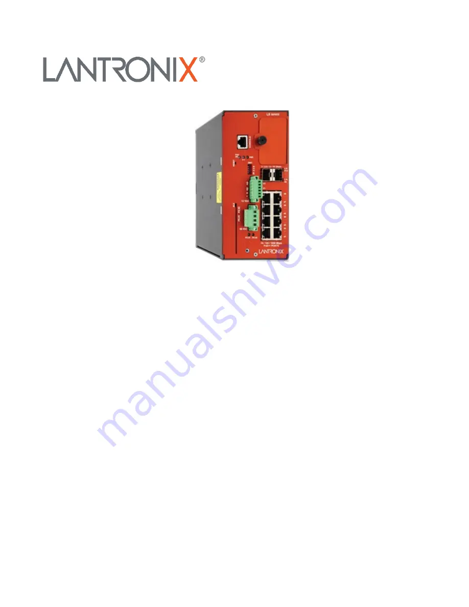
LSS2200-8P
Managed Layer 2 Gigabit Ethernet PoE++ Switch
(8) 10/100/1000Base-T IEEE 802.3bt + (2) 10G/5G/2.5G/1G SFP+ Multi-Gig Slots
Install Guide
Part Number 33860
Revision A October 2022
Page 1: ...LSS2200 8P Managed Layer 2 Gigabit Ethernet PoE Switch 8 10 100 1000Base T IEEE 802 3bt 2 10G 5G 2 5G 1G SFP Multi Gig Slots Install Guide Part Number 33860 Revision A October 2022 ...
Page 2: ...2 or Email https www lantronix com technical support Sales Offices For a current list of our domestic and international sales offices go to www lantronix com about contact Disclaimer All information contained herein is provided AS IS Lantronix undertakes no obligation to update the information in this publication Lantronix does not make and specifically disclaims all warranties of any kind express...
Page 3: ... 13 Electrical Safety Warnings 14 High Risk Activities Disclaimer 15 Recycling Disposal 15 Front Panel 16 RESET Button 16 LED Summary 17 Mounting Options 18 Mounting the Switch on a Table Desk Shelf or Other Flat Surface 18 Mounting the Switch on a Wall 18 DIN Rail Mount 19 Grounding the LSS2200 8P 19 Connecting to the CONSOLE Port 20 Connecting to a Management Port 20 Installing SFP Modules 20 Re...
Page 4: ...st Gasp 37 Always On PoE 37 3 Initial Switch Configuration 38 Connect and Log In to the Switch Using a Web Browser 38 4 Troubleshooting 39 Basic Troubleshooting 39 LED Troubleshooting 39 PoE Deployment 40 PoE Troubleshooting 41 Basic Steps 41 Additional Steps 41 Advanced Steps 42 Device Label and Box Label 43 Record Device and System Information 43 5 Related Information 45 Regulatory Agency Inform...
Page 5: ...ve building efficiency and enhance the tenant and guest experience within buildings The device comes pre enabled with easy to use Lantronix ConsoleFlow device management for the Cloud which allows users to find specific switches check device properties and scan through telemetry status data in real time from anywhere The Lantronix ConsoleFlow Cloud device manager provides cloud based control of yo...
Page 6: ...127 370 VDC Output 48 55 VDC 10A 480 Watts See the 25160 product page SFPs See the Lantronix SFP page OCA P181610 Outdoor Cabinet Assembly see https www lantronix com products oca p181610 WMB LSS Wall mount bracket kit optional Services order separately CF NWS CLOUDSAAS xYR ConsoleFlow Cloud Subscription x Years 1 3 or 5 years LEVEL x yYEAR Technical Support Services Level 1 2 or 3 and 1 3 or 5 ye...
Page 7: ...ways on PoE Ultra fast PoE ConsoleFlow Features Cloud Instance ConsoleFlow cloud instance integration provides Device configuration management Remote monitoring and diagnostics tools Device health dashboard and reporting Alarm notifications via email and text Lantronix Provisioning Manager LPM Features Device Discovery LPM discovers Lantronix IoT gateways and console managers on the local subnet a...
Page 8: ...5 Console port CLI port Cisco BLUE cable compliant pinning MAC Addresses 16K MAC address table Frame Buffer Memory 2 megabits per second Dimensions Width 3 313 84 14 mm x Depth 5 125 130 18 mm x Height 7 145 181 48 mm DIP Switch 1 Enable Disable PHO to PoE Power interlock see Note 2 Input 1 relay normal state not active 3 4 PoE power down selection Note for future use the current default is disabl...
Page 9: ...ways On PoE When enabled during switch warm restart it will continue providing PoE power to the PDs Ultra fast PoE Improves PoE startup time it provides PoE output to attached PDs within five seconds after a cold start PD compatibility Compatible with IEEE 802 3af at bt devices Force mode available for powering non standard PDs EMI FCC Class A CE UL62368 1 Safety Compliance UL cUL CB 62368 1 2nd E...
Page 10: ...Ingress Protection The switch provides IP31 rating per IEC 60529 EN 60529 for solid ingress protection 2 5mm and liquid ingress protection dripping water See the IEC webpage for more IP ratings information PHO PoE Hardware Override PHO provides a turn off of the PoE power delivery in the event of an external trigger Note that enabling the PHO function using DIP switch 1 dedicates both DIO interfac...
Page 11: ... Guide 33860 Rev A https www lantronix com 11 Applications Smart buildings for connection of high power PoE security cameras WAPs Private LTE Powering PoE lighting Security and Surveillance systems Distributed PoE for Led Lighting ...
Page 12: ...Lantronix LSS2200 8P Install Guide 33860 Rev A https www lantronix com 12 Traffic Management Distributed PoE for Outdoor Environments ...
Page 13: ...iceable parts Caution While installing or servicing the switch wear a grounding device and observe all electrostatic discharge precautions Failure to observe this caution could result in damage to or failure of the switch Warnings Warning Do not connect the switch to an external power source before installing it into its cabinet or mounting location Failure to observe this warning could result in ...
Page 14: ...nterminated ports or at fibers that connect to unknown sources Do not examine unterminated optical ports with optical instruments Avoid direct exposure to the beam Electrical Safety Warnings Electrical Safety IMPORTANT This equipment must be installed in accordance with safety precautions Elektrische Sicherheit WICHTIG Für die Installation dieses Gerätes ist die Einhaltung von Sicherheitsvorkehrun...
Page 15: ... requiring fail safe controls the operation of Nuclear Facilities Aircraft Navigation or Aircraft Communication Systems Air Traffic Control Life Support or Weapons Systems High Risk Activities Lantronix and its supplier s specifically disclaim any expressed or implied warranty of fitness for such High Risk Activities Recycling Disposal Do not discard electronic products in household trash All wast...
Page 16: ...P1 P8 10 100 1000 PoE Ports Ground screw hole PS 1 and PS 2 Power Supply 1 and 2 LEDs 56 VDC Terminal connector for dual 56VDC input power BLE Bluetooth Low Energy connector RESET System reset button PHO On LED S1 LED and P Power LED CONSOLE Port Note PHO is currently Disabled by default do not override until fully supported RESET Button The RESET button is inset from the front panel Use a thin ob...
Page 17: ...n On Link at 10G Blinking Link Activity LED yellow On Link at 1G 2 5G 5G Blinking Link Activity System LEDs Power P LED green On Power on At power up Blinking boot up or re boot in progress After successful boot Blinking Firmware update in progress System S1 LED green On connected to cloud Blinking re establishing cloud connection System S1 LED yellow On no cloud connection Blinking cloud provisio...
Page 18: ...the poly bag remove the protective adhesive covering and place the rubber feet as required Mounting the Switch on a Wall A wall mount bracket kit WMB LSS optional sold separately with two 4 40 x 1 4 screws included which can be used to attach the bracket to the switch Note Due to variation in mounting surfaces mounting screws not provided A drawing of the bracket is shown below When mounting on a ...
Page 19: ...ding the LSS2200 8P The front panel provides for a grounding screw to be used for grounding the switch Grounding and wire routing help limit the effects of noise due to EMI electromagnetic interference Run the ground connection from the ground screw not provided to the grounding surface before connecting devices Note Both the switch and Power Supply must have their ground terminals connected to ea...
Page 20: ... See the Lantronix Copper SFP page for our line of copper SFP transceivers See the FOA webpage for additional information The Fiber Optic Association Inc is an international non profit educational association chartered to promote professionalism in fiber optics through education certification and standards Note The SFP ports should use UL Listed Optional Transceiver products Rated 3 3Vdc Laser Cla...
Page 21: ...W1 is shown and described below The figure below shows SW1 default settings The factory default setting is DIPs 1 4 set to UP 1 OPEN Left default setting DIP Description Position Up 1 Down 0 1 Enable Disable PHO to PoE Power interlock 1 PHO PoE Hardware Override function is Disabled default 0 PHO Enabled PHO provides a turn off of the PoE power delivery in the event of an external trigger Note tha...
Page 22: ...rately Additional Items Not shipped but may be required ESD preventive cord with wrist strap wire and wire crimper for chassis grounding Ethernet cables ratcheting torque flathead screwdriver that exerts up to 15 in lb 1 69 N m of pressure a 1 and a 2 Phillips screwdriver Cautions 1 The switch is an indoor device If you need to use it to connect outdoor devices such as outdoor IP cameras or outdoo...
Page 23: ...owing voltage if any of the ports require the corresponding PoE levels IEEE 802 3af min 46VDC IEEE 802 3at min 52VDC IEEE 802 3bt min 54VDC Example If any port is providing IEEE 802 3bt to a powered device the power input must be at least 54VDC The recommended power supply for powering the LSS2200 8P and providing full power on all ports is part number 25172 Weidmuller Pro Max 960W 48V 20A power s...
Page 24: ...raw more power from the external supply than it is capable of providing and results could be detrimental Note The power supply wattage value s must be manually set in the software by the user to match the connected external power supply ies The LLSS2200 8P uses this wattage as the PSE Power Available to determine if enough power is available during PoE PD classification to power up connected PDs L...
Page 25: ...ix com 25 Single Power Supply Applications If using a single power supply either terminal block input PS1 or PS2 can be used to power the switch In the case of power supply failure there is no backup power and the switch will cease to operate until power is restored ...
Page 26: ... on Each Supply If using dual power supplies with the same power rating wattage the output voltage of each supply should be set to the same nominal voltage within 0 5V for current sharing If there is a 2V difference in the setting of the power supplies most or all of the power will be sourced from the higher voltage supply ...
Page 27: ...the primary power supply the switch will start drawing power from the backup supply and the new backup power budget will be evaluated by the switch If the budget is in violation the ports will be powered down by priority low then high then critical priority until the power budget is no longer in violation Within each priority ports will be powered down in order from lowest to highest port number W...
Page 28: ... weight 3 950 g 8 7 Lbs 25172 Input data Nominal input voltage wide range input 100 240 V AC Input voltage range AC 85 277 V AC Frequency range AC 45 65 Hz Input voltage range DC 80 370 V DC Current consumption 4 52 A 230 V AC 10 A 115 V AC Current consumption DC 2 8 A 370 V DC 10 A 120 V DC Max start up current 15 A 230 V AC Input fuse internal Yes Recommended back up fuse Safety cutout fuse Mini...
Page 29: ...e 0 5 0 6 Nm 1 2 1 5 Nm Insulation stripping length 6 mm 6 mm 25172 EMC shock vibration Interference radiation acc to EN 55022 Class B Interference immunity tests acc to EN 61000 4 2 ESD EN 61000 4 3 EN 61000 4 4 Burst EN 61000 4 5 Surge EN 610004 6 conducted EN 61000 4 8 Fields EN 61000 4 11 Dips Limiting of mains harmonic currents acc to EN 61000 3 2 Shock resistance in all directions Vibration ...
Page 30: ...ocation of sufficient ventilation 50 mm clearance for air intake from above and below Installation on a mounting rail in compliance with DIN 50022 35 in housing that is appropriate for the environmental conditions Take particular care with the installation position B 25172 Connection The electrical connection should only be carried out by a qualified technician These points must be observed The en...
Page 31: ...ction is required NOTICE When the 25172 internal fuse is triggered the probable cause is an internal malfunction The device must then be inspected in the factory D 25172 IV curve The power supply unit has an IV curve This allows it to be operated safely even in short circuit spans without a shutoff mechanism no hick up The device returns immediately to routine operations after the short circuit ha...
Page 32: ...cteristics These power supply units are designed to operate in a temperature range of 25 to 70 C A derating of 2 5 K takes effect above 60 C The unit will shut off if it overheats as a result of excessive environmental conditions It will then automatically restart after the necessary cool down period ...
Page 33: ...nix com 33 25172 Weidmuller PRO MAX 960W 48V 20A Views The 25172 ships from the factory set to 48V Set the front panel Adjust screw to the voltage required for your application See Power Supply Information on page 23 and Power Input on page 23 for more information ...
Page 34: ...0 Line Regulation 0 5 Load Regulation 1 0 Setup Rise Time 300ms 60ms Hold Up Time 20ms Input Voltage Range Switch Selectable 90 264VAC 127 370VDC Frequency Range 47 63H Efficiency 94 AC Current Typical 5A 115VAC 2 5A 230VAC Inrush Current Cold 40A 115VAC 80A 230VAC Protection Overload 110 160 Overvoltage 57 6 64 8V Environment Operating Temp 25 C to 70 C Storage Temp 40 C to 85 C Humidity 20 to 90...
Page 35: ...Lantronix LSS2200 8P Install Guide 33860 Rev A https www lantronix com 35 25160 Dimensions Width 3 37 85 5 mm x Depth 5 06 128 5 mm x Height 5 99 152 2 mm ...
Page 36: ... o Voltage max 34V Power supply o 12V at 70mA maximum Tolerance Min 11 2V Max 13 2V The Digital I O can be configured via the Web UI or the CLI See the related sections of this manual for more information Connecting to DC Power The front panel terminal block allows connection of one or two supported 56VDC power supplies 1 Make sure that you ground the enclosure before you install the terminal bloc...
Page 37: ...load This does not keep up the PoE power delivery Always On PoE The Always On PoE feature allows a warm reboot of the switch without affecting the PoE output to attached PDs providing continuous PoE power even during firmware upgrade Sometimes PoE momentarily stops being provided It is common for PoE to stop being provided by the LSS2200 8P for a 6s period beginning 2 5 minutes after a reboot is i...
Page 38: ...ration stage you must reconfigure your PC s IP address and subnet mask so as to make sure the PC can communicate with the switch The switch default IP address is 192 168 60 1 so the PC needs a different IP address in that subnet as described in step 2 in the procedure below The initial Username is admin and the initial Password is ltrx admin You should change the password as soon as possible becau...
Page 39: ...click on the blue floppy disk icon in the top right hand corner of the webpage and try a power reset again 17 Check the LSS2000 8P product page for possible newer firmware check the related Release Notes for enhancements or fixes to your problem 18 Record Device and System Information on page 53 19 Contact Lantronix Technical Support LED Troubleshooting The following table provides information to ...
Page 40: ...y suggested to install a surge protector or surge suppressor to protect the switch The switch is compliant with 802 3at in Environment A when using an isolated power supply For 802 3at Environment B applications i e building to building copper to copper endpoint connections 1 use an Ethernet network isolator module PoE disabled or 2 use mid span injector s e g MIL L100i L1000i at between this swit...
Page 41: ... switch port is properly connected to the PD Check if PDs work on other PoE ports Check if other PDs work on this PoE port Check your RJ 45 outlet for power using a PoE AF AT BT tester Verify the PoE parameter selections in the Web Ui or CLI Check the port configuration parameters in the Web Ui or CLI Additional Steps 1 Note that this product is to be connected only to UL listed PoE networks and w...
Page 42: ...nnection points in the transmission path b 90 meters of solid strand Category 5 or 5e and c 10 meters of flexible multistrand cable 2 to 5 meters of multistrand Category 5 patch cords 7 Verify that the PSE switch power budget can power the PD If the switch power budget is depleted additional PDs will not power on when connected to a PoE port Verify that the switch power budget available PoE is not...
Page 43: ..._________ Hardware Version ___________________ Mechanical Version _______________________________ Firmware Version ____________________ System Date ______________________________________ 3 Record the LED Status ________________________________________________________________ ______________________________________________________________________________________ _____________________________________...
Page 44: ...____________________________________________ A description of your network environment layout cable type etc ___________________________________ _________________________________________________________________________________________ _________________________________________________________________________________________ ___________________________________________________________________________...
Page 45: ...55032 2015 A11 2020 FCC Part 15 Subpart B Class A Conducted Emissions EN 55032 2015 A11 2020 Specification Clause Test Description Base Standard EN 55035 4 2 1 Electrostatic discharges ESD EN 61000 4 2 EN 55035 4 2 2 2 Continuous RF electromagnetic field disturbances EN 61000 4 3 EN 55035 4 2 2 3 Continuous induced RF disturbances EN 61000 4 6 EN 55035 4 2 3 Power frequency magnetic field EN 61000...
Page 46: ...8 1 EN62368 1 2011 65 EU EN 50581 2012 EN 55011 2009 A1 2010 Group 1 Class A EN 55024 2010 EN 61000 6 2 2005 EN55022 EN61000 6 4 EN55024 EN61000 6 2 IEC EN61000 4 2 IEC EN61000 4 3 IEC EN61000 4 4 IEC EN61000 4 5 IEC EN61000 4 6 IEC EN61000 4 8 IEC60068 2 27 IEC60068 2 32 and IEC60068 2 6 With the technical construction on file at the above address this product carries the CE Mark I the undersigne...
Page 47: ... Discovery Suite 250 Irvine CA 92618 USA Toll Free 800 526 8766 Phone 949 453 3990 Fax 949 453 3995 Technical Support Online https www lantronix com technical support Sales Offices For a current list of our domestic and international sales offices go to the Lantronix web site at www lantronix com about contact ...