background image

Configuration

Serial Channel (Port) Configuration

7-7

Interface Mode

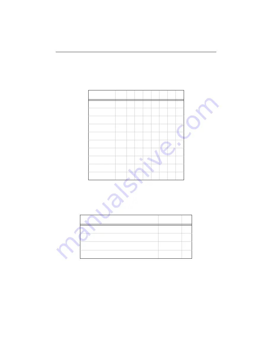
The Interface (I/F) Mode is a bit-coded byte entered in hexadecimal notation. Use the
following table to select Interface Mode settings:

Note:

Embedded units require external serial drivers to support RS-232 or
RS-485.

The following table demonstrates how to build some common Interface Mode settings:

Note:

See Binary to Hexadecimal Conversion on page E-18 for more
information on converting binary values to hexadecimal format.

Table 7-1: Interface Mode Options

Option

Bit 7 6

5

4

3

2

1

0

RS-232C

0

0

RS-422/485

0

1

RS-485 2-wire

1

1

7 Bit

1

0

8 Bit

1

1

No Parity

0

0

Even Parity

1

1

Odd Parity

0

1

1 Stop bit

0

1

2 Stop bits

1

1

Table 7-2: Common Interface Mode Settings

Option

Binary

Hex

RS-232C, 8-bit, No Parity, 1 stop bit

0100 1100

4C

RS-232C, 7-bit, Even Parity, 1 stop bit

0111 1000

78

RS-485 2-Wire, 8-bit, No Parity, 1 stop bit

0100 1111

4F

RS-422, 8-bit, Odd Parity, 2 stop bits

1101 1101

DD

Summary of Contents for CoBox-Micro

Page 1: ...ni100 UDS 10B Revision C 1 02 Part Number 900 226 Copyright and Trademark Copyright 2000 Lantronix All rights reserved No part of the contents of this book may be transmitted or reproduced in any form or by any means without the written permission of Lantronix Printed in the United States of America ...

Page 2: ...radiate radio frequency energy and if not installed and used in accordance with this guide may cause harmful interference to radio communications Operation of this equipment in a residential area is likely to cause interference in which case the user at his or her own expense will be required to take whatever measures may be required to correct the interference Changes or modifications to this dev...

Page 3: ...rd Layout 2 1 Connectors 2 2 RJ45 Connector 2 3 Status LEDs 2 4 Product Information Label 2 5 Test Bed 2 5 Test Bed Connectors 2 6 Chapter 3 CoBox Mini Overview 3 1 Board Layout 3 2 Connectors 3 2 Status LEDs 3 4 Product Information Label 3 4 Test Bed 3 5 Test Bed Connectors 3 6 Chapter 4 CoBox Mini100 Overview 4 1 Board Layout 4 1 Connectors 4 2 Status LEDs 4 4 Product Information Label 4 4 Test ...

Page 4: ...iguration Using a Telnet Connection 7 2 Serial Configuration 7 2 Network Configuration Using UDP 7 3 Network Configuration Using a Hex File 7 3 Configuration Parameters 7 4 Server Configuration 7 5 IP Address 7 5 Gateway Address 7 5 Subnet Mask 7 5 Telnet Configuration Password 7 5 DHCP Naming 7 6 Serial Channel Port Configuration 7 6 Baud Rate 7 6 Interface Mode 7 7 Flow Control 7 8 Port Number 7...

Page 5: ...r 8 Using the Device Server Comm Port Redirector 8 1 Redirector Setup 8 1 Device Server Configuration 8 1 Chapter 9 Serial Timing Hardware 9 1 Chapter 10 Integration Guidelines Test Environment 10 1 First Setup 10 1 Second Setup 10 1 EMI test results 10 2 General Guidelines 10 5 Appendix A Contact Information Problem Report Procedure A 1 Full Contact Information A 2 Corporate Offices A 2 Sales Off...

Page 6: ...k Configuration Using UDP E 1 Network Configuration Using a Hex File E 3 Acquiring a Valid Setup Record E 3 Sending a Setup Record E 4 The Intel Hex Format E 5 Calculating the Checksum E 6 Setup Records E 7 Channel Parameters E 8 IP Addresses E 14 Network Portion E 14 Subnet Portion E 15 Host Portion E 15 Network Address E 15 Broadcast Address E 15 IP Subnet Mask E 16 Private IP Networks and the I...

Page 7: ...ni100 and CoBox Micro embedded Device Servers These kits allow software engineers to test our Device Servers with their products prior to the hardware development of those products Each kit contains an embedded Device Server board carrier unit and all the connectors and data needed to interface our product with your serial device The Embedded Integration Kits include the following An embedded Devi...

Page 8: ...vices Security Alarms and Access Control Devices Handheld Instruments Device Servers connect these devices through a TCP data channel or through a Telnet connection to computers or other Device Servers Datagrams can be sent by UDP Network Protocols Device Servers use IP protocol for network communications The supported protocols are ARP UDP TCP ICMP Telnet TFTP DHCP HTTP SNMP and BOOTP For connect...

Page 9: ...nd sixth bytes are unique numbers assigned to each Device Server Table 1 1 Sample Ethernet Address Internet Protocol IP Address Every device connected to an IP network must have a unique IP address This address is used to reference the specific Device Server See Appendix E for more information on IP Addressing Port Numbers Every TCP connection and every UDP datagram is defined by a destination IP ...

Page 10: ......

Page 11: ...ls such as ARP UDP TCP Telnet BOOTP ICMP SNMP DHCP TFTP and HTTP as well as other custom protocols The CoBox Micro also supports a variety of user configurable options such as buffer control and packetization which make it easy to use in most applications Board Layout Figure 2 1 CoBox Micro Board Layout Alternate construction without LED RJ45 Connector 1 575 1 935 1 370 100 100 625 400 150 465 Not...
Page 12: ...g each connector can be specified as follows Pins 5 46mm on off the board and top bottom LEDs on off the board RJ45 on off the board Contact Lantronix for information about ordering Device Servers with customized connector configurations The Embedded Integration Kit part number Micro Kit includes the CoBox Micro embedded Device Server Refer to the following table for a listing of its pinouts CON3 ...

Page 13: ...SE T RJ45 Connector CON3 SIL 2 x 2 Pins in place of RJ45 CON4 SIL 2 x 4 Pins in place of LEDs Pin Signal Pin Signal Pin Signal Pin Signal 1 2 3 4 5 6 7 8 9 10 11 12 5VDC GND RxA input TxA output RTSA output DTRA output CTSA input DCDA input Reserved RESET pull low to reset RxB input TxB output 1 2 3 4 5 6 7 8 Tx Tx Rx None None Rx None None 1 2 3 4 Tx Tx Rx Rx 1 2 3 4 5 6 7 8 5VDC 5VDC LED3 Diagno...

Page 14: ...Port Channel 2 Status CON 4 Pin 7 Lights solid yellow to indicate Channel 2 is idle Blinks yellow to indicate Channel 2 is connected to the net work and active 3 Diagnostics CON 4 Pin 3 Blinks or lights solid red in combination with the green Channel 1 LED to indicate diagnostics and error detection Red solid green Channel 1 blinking 1x EPROM checksum error 2x RAM error 3x Network controller error...

Page 15: ...Kit includes a test bed carrier board that provides serial connections to the Device Server The network 10 Base T RJ45 is provided by the CoBox Micro Device Server The test bed contains LEDs a voltage regulator a power supply circuit a reset switch TTL to RS 232 and RS 232 to TTL conversion hardware and jumpers for various configuration options The test bed allows software engineers to immediately...

Page 16: ...al 6VDC The 3 pin header next to J1 is the second serial port Table 2 3 CoBox Micro Test Bed Connector Pinouts CON1 Serial Port Channel 1a a CON1 Serial Port Channel 1 is also designated as A CON2 TTL Interface CON4 Serial Port Channel 2b b CON4 Serial Port Channel 2 is also designated as B Pin Signal Pin Signal Pin Signal 1 2 3 4 5 6 7 8 9 DTRA output TxA output RxA input DCDA input GND None CTSA...

Page 17: ...ut Configurations CON1 Serial Port CON2 TTL Interface 5 1 9 6 GND DTRA out RxA in TxA out DCDA in RTSA out CTSA in 1 2 11 12 5VDC TxA out RxA in GND CTSA in DCDA in RTSA out DTRA out TxB out RxB in TxB out RxB in GND CON4 Serial Connector 1 3 ...

Page 18: ......

Page 19: ...requires 5 volts DC of regulated power with maximum current of 200mA for normal operation The CoBox Mini s well developed IP firmware supports protocols such as ARP UDP TCP BOOTP Telnet ICMP SNMP DHCP TFTP and HTTP as well as other custom protocols The CoBox Mini also supports a variety of user configurable options such as buffer control and packetization which make it easy to use in most applicat...

Page 20: ...CON4 At the time of ordering each connector can be specified with the following pin configurations Not present Top mounted length of 5 46 mm or 6 76 mm Bottom mounted length of 5 46 mm or 6 76 mm CON1 CON4 CON2 CON3 10 5 0 413 mm in Units 9 8 0 386 3 5 0 138 2 54 0 1 3 0 0 118 4x 2 5 0 098 75 0 2 953 80 0 0 20 3 150 0 008 2 54 0 100 2 5 0 098 15 9 0 626 5 08 0 2 2 7 0 106 65 0 2 559 70 0 0 2 2 756...

Page 21: ...N1 TTL Serial Port CON4 TTL Serial Port with Full Handshaking CON2 AUI Connector CON3 10BASE T Connector Pin Signal Pin Signal Pin Signal Pin Signal RJ45 1 2 3 4 5 6 7 8 9 10 5VDC GND TxA output RxA input RESET pull low to reset DCDA input LED1 Channel 1 LED2 Channel 2 LED3 Diagnostic 5VDC for LEDs 1 2 3 4 5 6 7 8 9 10 DTRA output GND RxB input TxB output CTSA input CTSB input RTSA output DTRB out...

Page 22: ... green to indicate Serial Port Channel 1 is idle Blinking green to indicate Channel 1 is connected to the network and active 2 Serial Port Channel 2 Status CON1 Pin 8 Steady yellow to indicate Channel 2 is idle Blinking yellow to indicate Channel 2 is connected to the network and active 3 Diagnostic CON1 Pin 9 Steady or blinking red in combination with the green Channel 1 LED to indicate diagnosti...

Page 23: ...r supply circuit a reset switch TTL to RS 232 and RS 232 to TTL conversion hardware The test bed allows software engineers to immediately begin developing and testing software applications for the Device Server rather than delaying the process until the hardware interface for their product is complete Figure 3 3 CoBox Mini Test Bed CON9 CON1 PWR CON7 CH1 CON8 CH2 CON4 1 8 Link 10 1 6 1 5 9 6 1 5 9...

Page 24: ... Serial Port Channel 1a a Serial Port Channel 1 is also designated as A CON8 Serial Port Channel 2b b Serial Port Channel 2 is also designated as B CON9 AUI Connector Pin Signal Pin Signal Pin Signal Pin Signal 1 2 3 4 5 6 7 8 Tx Tx Rx Decoupling Decoupling Rx Decoupling Decoupling 1 2 3 4 5 6 7 8 9 DCDA input RxA input TxA output DTRA output GND None RTSA output CTSA input None 1 2 3 4 5 6 7 8 9 ...

Page 25: ...x 3 Rx 6 Rx CON8 Serial Connector CON9 AUI Connector 5 1 9 6 GND DCDA in RxA in TxA out DTRA out RTSA out CTSA in 5 1 9 6 GND DCDB in RxB in TxB out DTRB out RTSB out CTSB in 1 9 8 15 GND GND GND GND GND COL Tx Rx COL Tx Rx 12VDC CON4 RJ45 Connector CON7 Serial Connector ...

Page 26: ......

Page 27: ... product s architectural requirements The CoBox Mini100 requires 5 volts DC of regulated power with maximum current of 250mA for normal operation The CoBox Mini100 s well developed IP firmware supports protocols such as ARP UDP TCP BOOTP Telnet ICMP SNMP DHCP TFTP and HTTP as well as other custom protocols The CoBox Mini100 also supports a variety of user configurable options such as buffer contro...

Page 28: ...t the time of ordering each connector can be specified as follows Not present Top mounted length of 5 46 mm or 6 76 mm Bottom mounted length of 5 46 mm or 6 76 mm Contact Lantronix or visit our Web site www lantronix com for information about ordering Device Servers with various connector configurations Figure 4 2 CoBox Mini100 Connector Layout 1 1 1 7 11 1 10 10 CON2 CON3 ...

Page 29: ...inouts CON1 TTL Serial Port CON4 TTL Serial Port CON3 10 100BASE T Connector Pin Signal Pin Signal Pin Signal RJ45 1 2 3 4 5 6 7 8 9 10 5VDC GND TxA output RxA input RESET pull low to reset DCDA input LED1 Channel 1 LED2 Channel 2 LED3 Diagnostics 5VDC for LEDs 1 3 1 2 3 4 5 6 7 8 9 10 DTRA output GND RxB input TxB output CTSA input CTSB input RTSA output DTRB output DCDB input RTSB output 1 2 3 4...

Page 30: ...nnel 1 is idle Blinks green to indicate Channel 1 is connected to the net work and active 2 Serial Port Channel 2 Sta tus CON1 Pin 8 Lights solid yellow to indicate Channel 2 is idle Blinks yellow to indicate Channel 2 is connected to the network and active 3 Diagnostic CON1 Pin 9 Blinks or lights solid red in combination with the green Channel 1 LED to indicate diagnostics and error detec tion Re...

Page 31: ...ower supply circuit a reset switch TTL to RS 232 and RS 232 to TTL hardware conversion The test bed allows software engineers to immediately begin developing and testing software applications for the Device Server rather than delaying the process until the hardware interface for their product is complete Figure 4 3 CoBox Mini100 Test Bed CON1 PWR CON7 CH1 CON8 CH2 CON4 1 8 11 Link 1 10 1 5 9 6 1 5...

Page 32: ...ts CON4 10 100Base TX RJ45 CON7 Serial Port Channel 1a a CON7 Serial Port Channel 1 is also designated as A CON8 Serial Port Channel 2b b CON8 Serial Port Channel 2 is also designated as B Pin Signal Pin Signal Pin Signal 1 2 3 4 5 6 7 8 Tx Tx Rx Decoupling Decoupling Rx Decoupling Decoupling 1 2 3 4 5 6 7 8 9 DCDA input RxA input TxA output DTRA output GND None RTSA output CTSA input None 1 2 3 4...

Page 33: ...4 4 Pinout Configurations 1 8 1 Tx 2 Tx 3 Rx 6 Rx CON7 Serial Connector CON8 Serial Connector 5 1 9 6 GND DCDA in RxA in TxA out DTRA out RTSA out CTSA in 5 1 9 6 GND DCDB in RxB in TxB out DTRB out RTSB out CTSB in CON4 RJ45 Connector ...

Page 34: ......

Page 35: ...addition an RJ45 10BASE T connector is available for Ethernet access It will support network speeds of 10Mbps The UDS 10B board comes with various power supply options a power jack for 9 30 VDC or 9 24 VAC with maximum 140mA power via the DB25 inputs at either the regulated 5 VDC with maximum 200mA or the unregulated 9 30 VDC The UDS 10B s well developed IP firmware supports protocols such as ARP ...

Page 36: ...Board Layout UDS 10B 5 2 Board Layout Figure 5 1 UDS 10B Board Layout mm in Units ...

Page 37: ... 485 2 wire functionality pins 14 and 21 and pins 15 and 22 must be connected to each other TX out 1 14 GND DCD out RTS in DSR out RX out 13 25 TX in RX in RX in TX out DTR in CTS out RS 485 422 RS 232C The Device Server can alternately be powered up via the serial port using one of these pins Reg 5VDC Unreg 9 30VDC The minus sign is sometimes represented as A e g TXA The plus sign is sometimes re...

Page 38: ...Interface UDS 10B 5 4 Network Interface The UDS 10B has a 9 30VDC power plug a reset switch and an RJ45 10Base T Ethernet port that supports 10 Mbps Figure 5 3 UDS 10B Network Interface 1 8 1 Tx 2 Tx 3 Rx 6 Rx ...

Page 39: ...reen Status LED to indicate diagnostics and error detection This code should only appear after power up Even though the Device Server is going into operation mode the problem will potentially persist Red diagnostic solid green Status LED blinking 1x EPROM checksum error 2x RAM error 3x Network controller error 4x EEPROM checksum error 5x Duplicated IP address on the network 6x Software does not ma...

Page 40: ...on Label A product information label is located on of the UDS 10B and contains the following information about your specific unit Bar Code Serial Number Product ID name Product Description Ethernet Address also referred to as Hardware Address or MAC Address ...

Page 41: ...led The system manager will not be able to access the unit This port can also be password protected Only one terminal at a time can be connected to the serial port In RS 485 mode the Device Server is capable of multidrop connections Default IP Address The Device Server ships with a default IP address set to 0 0 0 0 which automatically enables DHCP within the Device Server Provided a DHCP server ex...

Page 42: ...ists but denies the Device Server an IP address the Device Server does not attach to the network but waits and retries AutoIP allows a small network of AutoIP enabled devices to be set up without any need for a DHCP server or static IP addresses AutoIP can be disabled by setting the IP address to 0 0 1 0 The 1 in the third octet is the disabling factor Setting the IP Address The Device Server s IP...

Page 43: ... network to build a new entry in the ARP table the IP address must be a host other than the machine on which you are working Once there is at least one additional entry in the ARP table use the following command to ARP an IP address to the Device Server Figure 6 3 ARP on Windows 2 Now open a Telnet connection to port 1 The connection will fail quickly 3 seconds but the Device Server will temporari...

Page 44: ...s blinking You have one second to enter three lowercase x characters Note The easiest way to enter Setup Mode is to hold down the x key at the terminal while powering up the Device Server 3 Select 0 Server Configuration and follow the prompts until you get to IP address 4 Enter the new IP address 5 Select 9 to save the configuration and exit Setup Mode The Device Server performs a power reset Usin...

Page 45: ...twork Use a Hex file to configure the unit over the network The Device Server s configuration is stored in nonvolatile memory NVRam and is retained without power The configuration can be changed at any time The Device Server performs a reset after the configuration has been changed and stored Network Configuration Using a Web Browser If your Device Server already has an IP address see Chapter 6 Ge...

Page 46: ...t menu click Run and type the following command where x x x x is the IP address and 9999 is the Device Server s fixed network configuration port number Figure 7 3 Network Login Using Telnet Note Be sure to include a space between the IP address and 9999 Serial Configuration For local configuration a terminal or a PC running a terminal emulation program can be connected to the Device Server s seria...

Page 47: ...ration mode Note The easiest way to enter Setup Mode is to hold down the x key on your keyboard while powering up the Device Server Network Configuration Using UDP The Device Server can also be configured or queried over the network using UDP datagrams For more information see Network Configuration Using UDP on page E 1 Network Configuration Using a Hex File When configuring a number of Device Ser...

Page 48: ...11 MAC address 00 20 4A 54 10 03 Software version V4 30 001206 Press Enter to go into Setup Mode basic parameters Hardware Ethernet Autodetect IP addr 192 168 1 10 gateway 192 168 001 001 netmask 255 255 255 000 Security Telnet setup is enabled TFTP download is enabled Port 77FEh is enabled Web setup is enabled Enhanced password is disabled Encryption is disabled Channel 1 Baudrate 9600 I F Mode 4...

Page 49: ...ay address must be within the local network Subnet Mask A netmask defines the number of bits taken from the IP address that are assigned for the host section Note Class A 24 bits Class B 16 bits Class C 8 bits The Device Server prompts for the number of host bits to be entered then calculates the netmask which is displayed in standard decimal dot notation when the saved parameters are displayed fo...

Page 50: ...P name of the customer s own choosing up to 8 characters can also be designated This option can be set in the server configuration menu Figure 7 5 Server Configuration Menu Serial Channel Port Configuration Select 1 to configure the Device Server s channel specific parameters Baud Rate The Device Server and attached serial device such as a modem must agree on a speed or baud rate to use for the se...

Page 51: ...nary to Hexadecimal Conversion on page E 18 for more information on converting binary values to hexadecimal format Table 7 1 Interface Mode Options Option Bit 7 6 5 4 3 2 1 0 RS 232C 0 0 RS 422 485 0 1 RS 485 2 wire 1 1 7 Bit 1 0 8 Bit 1 1 No Parity 0 0 Even Parity 1 1 Odd Parity 0 1 1 Stop bit 0 1 2 Stop bits 1 1 Table 7 2 Common Interface Mode Settings Option Binary Hex RS 232C 8 bit No Parity 1...

Page 52: ...emotely initiating connections Range 1024 65535 Note Port numbers 14000 14009 are reserved exclusively for use with the Comm Port Redirector application see Comm Port Redirector on page 8 1 Port number 9999 is reserved exclusively for Telnet setup Port number 77FEh is reserved exclusively for configuration If the UDP mode is selected the port number functions as the UDP source port number for outg...

Page 53: ...xadecimal Conversion on page E 18 for more information on converting binary values to hexadecimal format Table 7 4 Connect Mode Options Option Bit 7 6 5 4 3 2 1 0 Incoming network Connection Never accept incoming 0 0 0 Accept incoming with DTR 0 1 0 Accept unconditional 1 1 0 Response Nothing quiet 0 Character response C conn D disconn N unreachable 1 Startup on serial connection No active startup...

Page 54: ...ere is a modem connected to a local PC and a modem connected to a remote machine A user must dial from the local PC to the remote machine accumulating phone charges for each connection Modem Mode allows you to replace modems with Device Servers and to use an Ethernet connection instead of a phone call without having to change communications applications and make potentially expensive phone calls N...

Page 55: ...ss used with an outgoing connection Remote Port The remote TCP port number must be set to use automatic connections This parameter defines the port number on the target host to which a connection is attempted Table 7 6 Modem Mode Commands Command Function ATDTx x x x pppp or ATDTx x x x pppp Makes a connection to an IP address x x x x and a remote port num ber pppp ATDTx x x x Makes a connection t...

Page 56: ...CoBox Micro CoBox Mini and CoBox Mini100 On DTE devices use DCD input instead of DTR 1 Ignore DTRa 0 Telnet mode and terminal type setupb b The CoBox will send the Terminal Type upon an outgoing connection 1 Channel port passwordc c A password is required for a connection to the serial port from the network 1 Hard disconnectd d The TCP connection will close even if the remote site does not acknowl...

Page 57: ...de options Note See Binary to Hexadecimal Conversion on page E 18 for more information on converting binary values to hexadecimal format Table 7 8 Flush Mode Options Function Bit 7 6 5 4 3 2 1 0 Input Buffer Serial to Network Clear active connection from serial 1 Clear passive connection from network 1 Clear at disconnect 1 Output Buffer Network to Serial Clear active connection from network 1 Cle...

Page 58: ...recognition of send characters Trailing Characters In some applications CRC Checksum or other trailing characters follow the end of sequence character this option helps to adapt frame transmission to the frame boundary Send Characters If send characters are enabled the Device Server interprets the sendchars as a 2 byte sequence if not set they are interpreted independently Table 7 9 Pack Control O...

Page 59: ... any awaiting characters to the TCP connection This minimizes the response time for specific protocol characters on the serial line for example ETX EOT etc Setting the first sendchar to 00 disables the recognition of the characters Alternatively the two characters can be interpreted as a sequence see Pack Control on page 7 14 Telnet Terminal Type This parameter appears only if the terminal type op...

Page 60: ...rmware Upgrade This setting defaults to the N No option The Y Yes option disables the use of TFTP to perform network firmware upgrades With this option firmware upgrades can be performed only by using a hex file over the serial port of the Device Server Disable Port 77FE Hex Port 77FE is a setting that allows OEMs and others to configure the Device Server remotely You may wish to disable this capa...

Page 61: ...www counterpane com Note If you select Y you must complete the settings To escape complete the settings and exit without saving Enable Enhanced Password This setting defaults to the N option which allows you to set a 4 character password that protects the Configuration Menu The Y Yes option allows you to set a 16 character password Factory Default Settings Select 7 to reset the Device Server s ser...

Page 62: ......

Page 63: ...on instructions are included on the distribution CD 2 In the Redirector s configuration screen select Port Setup and add as many COM ports as you need for example one for each Device Server 3 Under each port select Add IP and enter the IP address Host of the Device Server that you want to assign to that port and then enter the TCPPort number 3000 to 3009 Note Remember the TCPPort number You will n...

Page 64: ...2 Note When using the Redirector the Device Server does not change its serial port configuration to match the PC application s serial settings Ensure that the Device Server serial port s configuration matches the configuration of your serial device ...

Page 65: ...i100 conform to CMOS input output standards For protection a 220 Ohm resistor is used in series For the CoBox UDS 10B serial timing refer to the RS232 RS422 485 standards that are applicable see MAX 232 chip set requirements For further information visit Advanced Micro Devices AMD on the web and refer to their documentation Read the Am186ES Am188ES data sheet and User s Manual ...

Page 66: ......

Page 67: ...wn test requirements test boards can be obtained from Lantronix please contact OEM sales First Setup A preliminary scan was made in one of two types of sealed chambers One type of sealed chamber was prepared to reduce emission echo The other type was prepared to absorb reflection Either type of chamber is acceptable The antenna used was a broadband type EMCO biconilog 3142 connected to an Hewlett ...

Page 68: ...that the CoBox Micro UUT passed FCC class A limits as well as CISPR22 class A Highest emission outputs are at 80Mhz and 120Mhz leading to a margin of 5dB at 120Mhz to the more stringent CISPR22 class A limit Table 10 1 CoBox Micro Results Frequency MHz Field Strength EN55022 Level at 10m dBµV m Limit Class A dBµV m DELTA dB Remarks 40 015 21 53 40 00 18 47 60 003 27 75 40 00 12 25 80 008 30 26 40 ...

Page 69: ... 47 00 15 46 380 025 34 01 47 00 12 99 400 024 30 62 47 00 16 38 420 03 30 64 47 00 16 36 440 02 27 20 47 00 19 80 480 029 27 28 47 00 19 72 520 035 27 57 47 00 19 43 Table 10 2 CoBox Mini Results Frequency MHz Field Strength Level at 3 m dBµV m Limit FCC Class B dBµV m DELTA dB Remarks 35 30 29 96 40 00 10 04 37 66 29 73 40 00 10 27 40 01 34 24 40 00 5 76 60 01 36 95 40 00 3 05 80 02 35 31 40 00 ...

Page 70: ...9 260 03 35 55 46 00 10 45 261 16 32 28 46 00 13 72 271 72 34 03 46 00 11 97 Table 10 3 CoBox Mini100 Frequency MHz Field Strength Level at 3 m dBµV m Limit FCC Class B dBµV m DELTA dB Remarks 40 00 34 99 40 00 5 01 50 00 34 25 40 00 5 75 100 01 35 72 43 50 7 78 110 83 30 07 43 50 13 43 125 01 30 99 43 50 12 51 150 00 37 34 43 50 6 16 175 00 29 55 43 50 13 95 200 01 36 10 43 50 7 40 250 01 33 30 4...

Page 71: ...oltage provide ground to the appropriate connector header with a low inductance and low DC resistance path The best solution is a solid ground plane Place a de coupling capacitor pair as close as possible to the connector headers of the board s power supply We recommend a ceramic X7R material or equivalent value 0 022uF to 0 1uF and a low DC resistance electrolytic or tantalum value 10uF to 100uF ...

Page 72: ...ected to the RJ45s shield or to a virtual ground signal provided by the CoBox See also next section and product specific section Figure 10 1 Multi layer board strategy Virtual Ground The CoBox units provide a virtual ground at a plated mounting hole It is a ground imitation It uses the tap of two capacitors ceramic 0 1uF conducted symmetrically to ground and VCC In absence of a solid ground earth ...

Page 73: ...ransformer should be kept as short as possible For additional AUI guidelines please see also the transformer manufactures application notes CoBox Mini100 Take care when laying out the trace for the RJ45 We recommend the use of shields described in the Network Connector section above On the optional 11 pin header for the network connector additional termination for the unused wires of the cable is ...

Page 74: ......

Page 75: ...edge Base Web site at www support microsoft com directory Contact your dealer or Lantronix Technical Support at 800 422 7044 US or 949 453 3990 Technical Support is also available via Internet E mail at support lantronix com Problem Report Procedure When you report a problem please provide the following information Your name Your company name address and phone number Product model CoBox Mini CoBox...

Page 76: ... Europe Middle East and Africa Minervum 1707 4817 ZK Breda The Netherlands Phone 31 0 76 565 8176 Fax 31 0 76 565 8179 E mail eu_sales lantronix com France Phone 33 0 139 30 41 74 Fax 33 0 139 30 41 73 E mail eu_sales lantronix com Germany Phone 49 0 7720 3016 20 Fax 49 0 7720 3016 88 E mail eu_sales lantronix com Pacific Rim 46 East Coast Road East Gate 10 01 Singapore 428766 Phone 65 447 4222 Fa...

Page 77: ...one 949 450 7227 Fax 949 450 7231 E mail intsales lantronix com Technical Support Technical Support Phone 800 422 7044 or 949 453 7198 Fax 949 450 7226 FAQs Documentation and Firmware Downloads www lantronix com support E mail support lantronix com Europe Middle East and Africa Technical Support Phone 49 0 7720 3016 57 Fax 49 0 7720 3016 88 E mail eu_techsupp lantronix com ...

Page 78: ......

Page 79: ...A 0 prompt indicates that you have successfully entered Monitor Mode Entering Monitor Mode Via the Network Port To enter Monitor Mode using a Telnet connection 1 First establish a Telnet session to the configuration port 9999 The following message appears Figure B 1 Entering Monitor Mode Via the Network 2 Type M upper case 3 A 0 prompt indicates that you have successfully entered Monitor Mode Moni...

Page 80: ... from hex records PI x x x x Ping Ping Device Server with IP address x x x x to check device status AT ARP Table Show the Device Server s ARP table entries TT TCP Connection Table Shows all incoming and outgoing TCP connec tions NC Network Connection Shows the Device Server s IP configuration RS Reset Resets the Device Server s power SI xxx xxx xxx xxx yyy yyy yyy yyy Send Set IP Address Remotely ...

Page 81: ...he commands listed above will generate one of the following command response codes Table B 2 Command Response Codes Response Meaning 0 OK no error 1 No answer from remote device 2 Cannot reach remote device or no answer 8 Wrong parameter s 9 Invalid command ...

Page 82: ......

Page 83: ...ia the serial port You can also update the Device Server s internal Web interface CBXW COB via TFTP Reloading Firmware Via TFTP To download new firmware from a computer 1 Use a TFTP client to send a binary file to the Device Server CBX ROM to upgrade the Device Server s internal operational code and CBXW COB to upgrade its internal Web interface Note TFTP requires the ROM binary version of the Dev...

Page 84: ...x x is the receiving Device Server s IP address Figure C 2 Sending Firmware to Another Device Server 3 The Device Server performs a power reset after the firmware has been loaded Note You can only update the Device Server s internal Web interface using TFTP Reloading Firmware Via the Serial Port To download firmware from a computer via the Device Server s serial port 1 Enter Monitor Mode see Monit...

Page 85: ...ng will result in a corrupt program image and a nonfunctional Device Server This process may take up to 10 minutes when using the serial method 4 The following message displays when the firmware upgrade is complete Figure C 3 Firmware Upgrade Screen Display 5 The Device Server performs a power reset after the firmware has been loaded Note You can only update the Device Server s internal Web interf...

Page 86: ......

Page 87: ...le list technical information common to all four of these Device Servers Table D 1 Dimensions Micro H x W x D 0 682 x 1 574 x 1 929 in 17 27 x 40 0 x 49 0 mm Weight 0 8 lbs 0 35 Kg Mini and Mini100 H x W x D 0 282 x 3 150 x 2 756 in 7 27 x 8 00 x 70 0 mm Weight 0 09 lbs 0 04 Kg UDS 10B H x W x D 3 385 x 2 280 x 0 55 in 86 0 x 57 9 x 14 mm Weight 0 8 lbs 0 35 Kg ...

Page 88: ...7 or 8 data bits Stop bits 1 or 2 Parity odd even none Modem Control DTR DCD CTS RTS Flow Control XON XOFF software CTS RTS hardware None Management Internal web server SNMP read only Serial login Telnet login System Software downloadable from a TCP IP host TFTP or over serial port LEDs good link green network Transmit Receive Data yellow collision red diagnostics red status green channel 1 Compat...

Page 89: ...r the network using UDP datagrams The Device Server has a UDP listener set for port 30718 77FE Hex Responses from the Device Server are returned to the source port of the UDP packet The first three bytes of the UDP data block should be set to zero The fourth byte selects the function as described in the following table ...

Page 90: ... will not be overridden using FA See FD for this functionality FB Configuration Change Acknowledge None This block is sent back to the host requesting a configuration change FB After sending out this block the Device Server resets and uses the new configuration sent with the FA command FC Set IP Address First 8 bytes must be set to the string IP SETUP Hex 49 50 2D 53 45 54 55 50 Next 2 bytes have ...

Page 91: ...setup record of a properly configured Device Server via Monitor Mode easiest method Request the setup record of a properly configured Device Server via another Device Server on the network Build the setup record in software From a host PC request the setup record of a properly configured Device Server via UDP To copy the setup record of a properly configured Device Server 1 Configure a master Devi...

Page 92: ... configuration To build the setup record in software 1 Create a 120 byte setup record 2 Convert it to an Intel Hex record see The Intel Hex Format on page E 5 3 Copy the setup record into a text file and save it for future use To request the setup record of a properly configured Device Server via UDP 1 Configure a Device Server with the desired parameters and place it on the network 2 From a host ...

Page 93: ...eviously saved setup record to a Device Server via UDP from a host PC send the FA or FD datagram to the target Device Server see Network Configuration Using UDP on page E 1 Note The Device Server responds with the FB datagram Refer to the table The Intel Hex Format With this format 8 bit binary data can be sent and received as ASCII text The transmission is blocked in records and every record has ...

Page 94: ...e and taking the two s complement of the sum Note Do not include the leading colon or the checksum byte in the sum Example 0300300002337A1E Record length 03 3 bytes of data Address 0030 the 3 bytes will be stored at 0030 0031 and 0032 Record Type 00 normal data Data 02 33 7A Checksum 1E 03 00 30 00 02 33 7A E2 The two s complement of E2 is 1E See Calculating the Two s Complement below Calculating ...

Page 95: ...unit x x x x 04 Reserved 0 05 Flag BYTE Bit 7 Reserved 0 Bit 6 Set 1 for AUI 0 for 10BASE T CoBox Micro only Bits 5 0 Reserved 0 06 Number of host bits for subnetting if 0 matching standard netmask for Class A B C is used 07 Reserved 0 08 11 Telnet configuration password 0 if not used 12 15 Gateway IP address 0 0 0 0 if not used 16 63 48 byte Channel 1 parameters parameter setup Channel 1 see Tabl...

Page 96: ...te Intel 24 27 72 75 Remote IP address low high low high 28 76 Connect Mode see Table E 9 Connect Mode Options 29 77 Disconnect Mode see Table E 10 Disconnect Mode Options 30 78 Disconnect w inactivity time out minutes 00 if unused 31 79 Disconnect w inactivity time out seconds 00 if unused 32 33 80 81 Characters to trigger send immediately sendchar 34 82 Flush mode see Table E 11 Flush Mode Optio...

Page 97: ...to Hexadecimal Conversion on page E 18 for more information on converting binary values to hexadecimal format Table E 5 Interface Mode Options Option Bit 7 6 5 4 3 2 1 0 RS 232C 0 0 RS 422 485 0 1 RS 485 2 wire 1 1 7 Bit 1 0 8 Bit 1 1 No Parity 0 0 Even Parity 1 1 Odd Parity 0 1 1 Stop bit 0 1 2 Stop bits 1 1 Table E 6 Common Interface Mode Settings Option Binary Hex RS 232C 8 bit No Parity 1 stop...

Page 98: ...tput Generally flow control is not required if the connection is used to pass a blocked protocol with block sizes less than 1k ACK NAK and or speeds of 19200 or less Use the following table to select Flow Control options Table E 7 Baud Rate Settings Speed bps Hex 38400 00 19200 01 9600 02 4800 03 2400 04 1200 05 600 06 300 07 115200 08 57600 09 Table E 8 Flow Control Options Option Hex No flow con...

Page 99: ...cimal Conversion on page E 18 for more information on converting binary values to hexadecimal format Table E 9 Connect Mode Options Option Bit 7 6 5 4 3 2 1 0 Incoming network Connection Never accept incoming 0 0 0 Accept incoming with DTR 0 1 0 Accept unconditional 1 1 0 Response Nothing quiet 0 Character response C conn D disconn N unreachable 1 Startup on serial connection No active startup 0 0...

Page 100: ...can control line handling and network buffers with connection startup and disconnect You can also select between two different packing algorithms Use the following table to select Flush Mode options Table E 10 Disconnect Mode Options Option Bit 7 6 5 4 3 2 1 0 Disconnect with DTR drop 1 Ignore DTR 0 Telnet mode and terminal type setup 1 Channel port password 1 Table E 11 Flush Mode Options Functio...

Page 101: ...ng table to select Pack Control options Note See Binary to Hexadecimal Conversion on page E 18 for more information on converting binary values to hexadecimal format Table E 12 Pack Control Options Option Bit 7 6 5 4 3 2 1 0 Idle Time Force transmit 12ms 0 0 Force transmit 52ms 0 1 Force transmit 250ms 1 0 Force transmit 5sec 1 1 Trailing Characters None 0 0 One 0 1 Two 1 0 Send Characters Sendcha...

Page 102: ...is determined by the network type Class A B or C In most network examples the host portion of the address is set to zero Consider the IP address 36 1 3 4 This address is a Class A address therefore the network portion of the address is 36 0 0 0 and the host portion is 1 3 4 Table E 13 Network Portion of IP Address Network Class Network Portion of Address Class A First byte 2nd 3rd and 4th bytes ar...

Page 103: ... to a router on the local network Host Portion The host portion of the IP address is a unique number assigned to identify the host Network Address A host address with all host bits set to 0 addresses the network as a whole for example in routing entries Figure E 2 Sample Network Address Broadcast Address A host address with all host bits set to 1 is the broadcast address meaning for for every stat...

Page 104: ... and then calculates the netmask which is displayed in standard decimal dot notation for example 255 255 255 0 when saved parameters are displayed Table E 15 Standard IP Network Netmasks Network Class Network Bits Host Bits Netmask A 8 24 255 0 0 0 B 16 16 255 255 0 0 C 24 8 255 255 255 0 Table E 16 Netmask Examples Netmask Host Bits 255 255 255 252 2 255 255 255 248 3 255 255 255 240 4 255 255 25...

Page 105: ...e Server on an intranet you should use one of the reserved sub networks Consult your network administrator with questions about IP address assignment Network RFCs For more information about IP addresses refer to the following documents which can be located on the World Wide Web using one of the following directories or indices RFC 950 Internet Standard Subnetting Procedure RFC 1700 Assigned Number...

Page 106: ...e values ranging from 0 to F which are represented as 0 9 A for 10 B for 11 etc To convert a binary value for example 0010 0011 to a hexadecimal representation the upper and lower four bits are treated separately resulting in a two digit hexadecimal number in this case 4C Use the following table to convert values from binary to hexadecimal Table E 17 Binary to Hexadecimal Conversion Table Decimal ...

Page 107: ...onversion circuits Figure F 1 TTL RS232 DB 9 Circuit Note If you need just the DTR and DCD or RTS and CTS signals you can use only one Max232 chip Max232 Tx DCD Rx DTR GND RTS CTS DTE Configuration Max232 Circuit consists of 2 Max232 compatible chips 8 capacitors 1 DB 9 connector DB 9 male ...

Page 108: ...32 DB 25 Circuit Note If you need just the DTR and DCD or RTS and CTS signals you can use only one Max232 chip Tx Rx CTS GND DCD DTR DCE Configuration DSR Max232 Max 232 Circuit consists of 2 Max232 compatible chips 8 capacitors 1 DB 25 connector RTS ...

Page 109: ...isting contract between the parties Any such contract states the entire obligation of Lantronix The contents of this document shall not become part of or modify any prior or existing agreement commitment or relationship The information recommendation description and safety notations in this or other documents sup plied by Lantronix are based on general industry experience and judgment with respect...

Page 110: ......

Reviews: