background image


18 

Jumper Settings & Connector Pinout (Motherboard) 
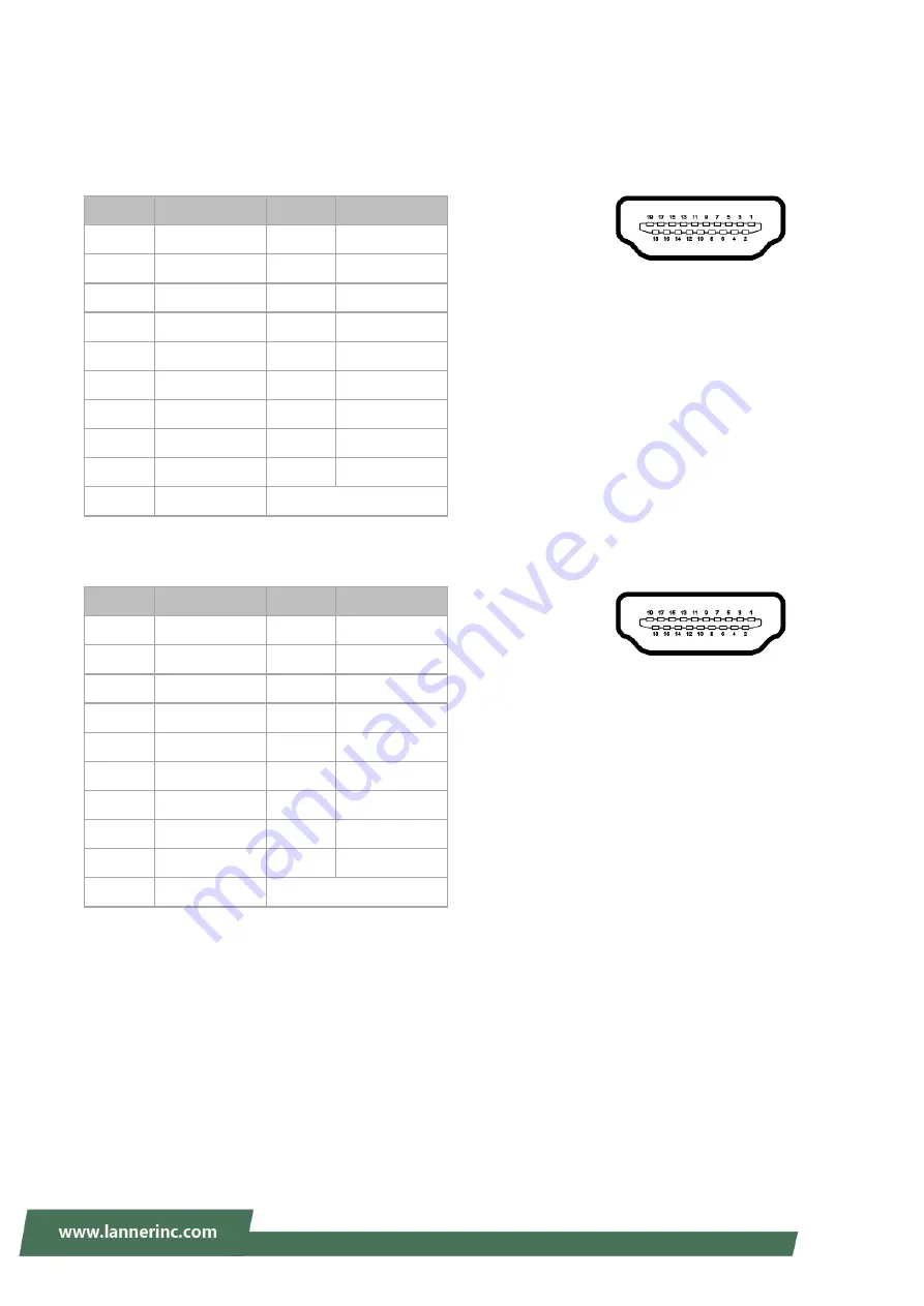
HDMI1

: High-Definition Multimedia Interface connector 


HDMI2

: High-Definition Multimedia Interface connector 


Pin No. 

Description 

Pin No. 

Description 

DATA2+ 

GND 

DATA2- 

DATA1+ 

GND 

DATA1- 

DATA0+ 

GND 

DATA0- 

10 

CLK+ 

11 

GND 

12 

CLK- 

13 

N.C 

14 

N.C 

15 

DDC CLK 

16 

DDC DAT 

17 

GND 

18 

HDMI_VCC 

19 

HPD 


Pin No. 

Description 

Pin No. 

Description 

DATA2+ 

GND 

DATA2- 

DATA1+ 

GND 

DATA1- 

DATA0+ 

GND 

DATA0- 

10 

CLK+ 

11 

GND 

12 

CLK- 

13 

N.C 

14 

N.C 

15 

DDC CLK 

16 

DDC DAT 

17 

GND 

18 

HDMI_VCC 

19 

HPD 


Summary of Contents for LEC-2580

Page 1: ...1 Embedded Computing Platform Hardware Platforms for Intelligent Edge Computing LEC 2580 User Manual Version 2 5 Version 1 7 Date of Release 2024 01 19...

Page 2: ...ion or warning and it is something that could damage your property or product Online Resources To obtain additional documentation resources and software updates for your system please visit the Lanner...

Page 3: ...s This document is copyrighted 2024 by Lanner Electronics Inc All rights are reserved The original manufacturer reserves the right to make improvements to the products described in this manual at any...

Page 4: ...Town Changping District Beijing 102208 China T 86 010 82795600 F 86 010 62963250 E service ls china com cn USA Lanner Electronics Inc 47790 Westinghouse Drive Fremont CA 94539 T 1 855 852 6637 F 1 510...

Page 5: ...ed to try to correct the interference by one or more of the following measures Reorient or relocate the receiving antenna Increase the separation between the equipment and receiver Connect the equipme...

Page 6: ...f used batteries according to the instructions Installation only by a skilled person who knows all Installation and Device Specifications which are to be applied Do not carry the handle of power suppl...

Page 7: ...the amount of airflow required for safe operation of the equipment is not compromised To avoid a hazardous load condition be sure the mechanical loading is even when mounting Consideration should be g...

Page 8: ...signes de s curit lectrique Avant d allumer l appareil reliez le c ble de mise la terre de l quipement la terre Une bonne mise la terre connexion la terre est tr s importante pour prot ger l quipement...

Page 9: ...ear I Os 16 CHAPTER 3 BOARD LAYOUT 17 Internal Jumpers Connectors 17 Jumper Settings Connector Pinout Motherboard 18 CHAPTER 4 HARDWARE SETUP 25 Accessing the Inside of LEC 2580 25 Installing SO DIMM...

Page 10: ...16GB Intel HD Graphics 2x HDMI display output ports 6x RJ45 LEC 2580 or 2x RJ45 4x PoE LEC 2580P 4x USB 3 0 and 2x USB 2 0 2x 2 5 HDD SSD with RAID 0 1 4x Serial Ports with RS 232 422 485 signals 0 C...

Page 11: ...LEC 2580P only Storage Type SATA III Installation 1x mSATA Socket Type SATA III Installation 2x 2 5 HDD SSD Drive Bay RAID 0 1 HDD SSD Thickness 2x 11mm or 1x 16mm I O Serial Port 4x RS 232 422 485 D...

Page 12: ...173 8 mm Construction Aluminum Weight TBD Mounting Wall DIN rail Rack VESA Driver Support Microsoft Windows WES7 Win 7 Pro FES WE 8 1 Industry Pro Win10 IoT Linux Kernel 3 12 Certification EMC CE FCC...

Page 13: ...13 CHAPTER 2 SYSTEM OVERVIEW Mechanical Drawing Unit mm...

Page 14: ...14 Block Diagram...

Page 15: ...E ports F2 USB Port 4x USB3 0 Type A ports in dual double stacked form F3 LED Indicator 2x LED for Power on status Green and Storage access status Yellow 2x LED for 3G WiFi communication access F4 Res...

Page 16: ...inal block support DC 24V input R2 Power Button 1x 2 pin terminal block for remote power on off R3 COM Port 4x D sub COM Ports with RS 232 422 485 signals R4 USB Port 2x USB 2 0 Type A Ports in double...

Page 17: ...17 CHAPTER 3 BOARD LAYOUT Internal Jumpers Connectors JTPM1 MSATA1 USB1 LAN1 6 USB2 JLPC HDMI1 2 JVGA1 SATA1 JSPI1 COM1 2 DIMM1 JME1 JCMOS1 POE1 SATAPWR1 2 CN1 USB3 ATX1 MPCIE1 MPCIE2 DIMM2...

Page 18: ...cription Pin No Description 1 DATA2 2 GND 3 DATA2 4 DATA1 5 GND 6 DATA1 7 DATA0 8 GND 9 DATA0 10 CLK 11 GND 12 CLK 13 N C 14 N C 15 DDC CLK 16 DDC DAT 17 GND 18 HDMI_VCC 19 HPD Pin No Description Pin...

Page 19: ...1 Active LED 12 Active LED yellow USB1 2 4 x USB3 0 Type A Connectors in dual double stacked form USB3 USB2 0 Type A Connectors in double stacked form PIN NO DESCRIPTION 1 USB_VCC1 2 USB 3 USB 4 GND 0...

Page 20: ...rrier Detect DCDA 6 Data Set Ready DSRA 2 Receive Data RXDA 7 Request To Send RTSA 3 Transmit Data TXDA 8 Clear To Send CTSA 4 Data Terminal Ready DTRA 9 Ring Indicator RIA 5 GND Pin Assignments for R...

Page 21: ...0 UIM_DATA 11 REFCLK 12 UIM_CLK 13 REFCLK 14 UIM_RESET 15 GND 16 UIM_VPP KEY 17 RSVD 18 GND 19 RSVD 20 W_DISABLE 21 GND 22 PERST 23 PERn0 24 3 3V 25 PERp0 26 GND 27 GND 28 1 5V 29 GND 30 SMB_CLK 31 PE...

Page 22: ...UIM_DATA 11 REFCLK 12 UIM_CLK 13 REFCLK 14 UIM_RESET 15 GND 16 UIM_VPP KEY 17 RSVD 18 GND 19 RSVD 20 W_DISABLE 21 GND 22 PERST 23 PERn0 24 3 3V 25 PERp0 26 GND 27 GND 28 1 5V 29 GND 30 SMB_CLK 31 PET...

Page 23: ...N C 9 GND 10 N C 11 N C 12 N C 13 N C 14 N C 15 GND 16 N C KEY 17 N C 18 GND 19 N C 20 N C 21 GND 22 N C 23 SATA_RXp 24 3 3V 25 SATA_RXn 26 GND 27 GND 28 N C 29 GND 30 N C 31 SATA_TXn 32 N C 33 SATA_T...

Page 24: ...Clear CMOS JME1 Flash ME Manageability Engine Short Pins Description 1 2 Normal Default 2 3 Flash ME SPI1 SPIROM Pin Header for Debug Purposes PIN DESCRIPTION PIN DESCRIPTION 1 SPI_HOLD 2 N C 3 SPI_CS...

Page 25: ...hock or damage to the equipment please remove all power sources Please wear ESD protected gloves before conducting the following steps Do NOT pile items on top of the system to prevent damages due to...

Page 26: ...MHz Please follow the steps below for proper installations 1 Locate the SO DIMM sockets on the motherboard 2 Select the socket for installing the module Align the memory module s key with the SO DIMM...

Page 27: ...and wireless modules Please follow the steps below for installations 1 Locate the mSATA and the mini PCIe sockets 2 Select the socket for installing the module Align the mechanical notches between th...

Page 28: ...wireless network module Please follow the steps below for installations 1 Locate the mini PCIe sockets 2 Align the mechanical notches between the module and the socket 3 Insert the LTE wireless netwo...

Page 29: ...s below for installation 1 Locate the dual 2 5 SATA HDD SSD drive bay at the back of the bottom compartment 2 Place disk drives onto the drive bay and apply two screws on each side of a SATA disk driv...

Page 30: ...o the wall 1 Ensure the wall brackets are properly fixed onto the chassis as illustrated in the drawings below 2 Please pay close attention to the dimensional parameters in the drawings below such as...

Page 31: ...it For purchasing a compatible rack mount shelf kit please reach out to our sales representative Contents of Rack Mount Shelf Kit This kit comes with screws for the assembly parts Power Adapter Bracke...

Page 32: ...32 1 To start please power off the system and remove the power cord 2 Remove the four rubber pads at the bottom compartment and replace them with the bottom panel screws supplied along with the kit...

Page 33: ...ill slightly differ based on the adapter type Below are the illustrations of the ideal screw position on the right mounting ear for different adapter types which will symmetrize the position on the le...

Page 34: ...the shelf using the provided screw s Power Adapter for non POE supported model For the power adapter for the non POE supported model please respectively lock a bracket on the front and the rear shelf...

Page 35: ...35 Power Adapter for POE supported model For the power adapter for the POE supported model please lock only one bracket on the front shelf the position of which is shown in the picture below...

Page 36: ...on the shelf make sure all the screws on each part are tightly and securely screwed 6 Carefully arrange the cable before you install this assembly into the server rack Power Adapter for non POE suppor...

Page 37: ...zero The software routinely resets this counter to prevent it from reaching zero However if the counter does hit zero indicating the software has failed to reset it the system assumes a software fail...

Reviews: