background image

Lanier - SHRIKE 40 - Instructions

Page 9

Copyright 1998 - Lanier R/C

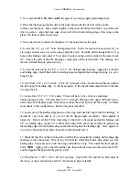
5. Assuming that the fuselage is painted or covered, peel off one side of the tape supplied.
Locate one end of the tape at the back edge of the nose block.  Place the rest down the center 
of the fuselage towards the tail.  Now pull off the rest of the paper and stick down the strip of 
plastic on it.  This skid will protect the bottom when landing.

6. Assemble and prepare the fuel tank for installation.  Cut a l' length of fuel line in two.  Place 
one piece in each of the fuel line holes in the firewall.  Pull them through until they can be hooked 
up to the tank.  One on the vent and one on the clunk line.  Wrap each line at the tank with a 
nylon zip tie to hold the lines on.

7. Now grab the two lines at the firewall and pull the tank into position.  Mount the tank as high 
as possible blocking it up with foam.

8. As a start, locate the receiver batteries under the fuel tank.  You may find it will be
necessary to shift it to another location when balancing at the CG shown on the plans.

9. Mount the throttle servo where shown.  Hook up the pushrod using the hardware specified 
not supplied.

10. Mount the aileron and elevator servos.  Hook them up with the hardware specified.  It will 
be necessary to make a slot in the section behind the aft edge of the hatch to accept the elevator 
pushrod.  You will have to put a slight bend in the rod to clear the hatch.  If you are using two 
aileron servos, mount the servos in the wings and run the wires into the fuselage.  Use (2) 4-40
control rod and an aileron horn set as shown on the plans.

11. Trim and install the canopy where shown on the hatch.  Use Zap New Formula 560
Canopy Glue to hold it in place.  If desirable install a pilot of your choice.

PRE-FLIGHT NOTES

Before the first flight, and to ensure some longevity in your Shrike 40, you will do well to check 
out a few things before heading to the flying field.

1. Balance the Shrike 40 at the indicated CG point shown on the plans with the fuel tank empty.
Depending on your type of flying you may want to adjust it forward some.

2. Check the control surface travels.  We have given you a starting point however, they need to 
be fine tuned to meet your flying needs.

3. Run the engine and check the idle.  Have it ready so you don't encounter any problems at the 
field.

Summary of Contents for MARINER 40 MK II ARF

Page 1: ...anier R C is proud of the care and attention that goes into the manufacture of parts for its model kits The company warrants that for a period of 30 days it will replace at the buyer s request any par...

Page 2: ...g experience to take on a built up model however every minute detail is not covered This is not a basic trainer The plans and instructions together with the laser cut parts and the simplicity of this...

Page 3: ...small end against F4 and pin in place over the wax paper Align the top curved edges and pin in place several places to keep aligned 7 Fold and crease the wax paper and trim off holding the razor again...

Page 4: ...on top and two on the bottom These are required to provide material when you round the nose to former Fl 15 Cut two more pieces 6 3 4 long Trim to size and glue these in between F2 and F3 flush with t...

Page 5: ...iling edge of the wing on the plans are perpendicular to the edge The side of the f uselage will be aligned with the work bench edge so it is important that things are square 1 Locate a 3 8 sq x 42 sp...

Page 6: ...ile the diamond shaped hole in the fuse to accept the LE 11 Locate four 3 32 x 3 x 36 sheets These will have to be cut to size and shape before gluing in place Cut each sheet to 24 in length Starting...

Page 7: ...d flush with each other Very few parts are required 1 Cut a 11 5 8 length from the 3 8 sq stick Install it in the 3 8 hole in the fuselage side against the wing trailing edge Center it leaving a equal...

Page 8: ...a final sanding depending on how well you want to finish it IMPORTANT glue a piece of 2 1 2 nylon glass tape GOLDBERG 451 along the upper and lower joints between the wing and the fuse with CA as show...

Page 9: ...throttle servo where shown Hook up the pushrod using the hardware specified not supplied 10 Mount the aileron and elevator servos Hook them up with the hardware specified It will be necessary to make...

Page 10: ...it a good range check 5 Check all hardware to be sure it is secure There is nothing worse than losing an airplane on the first flight because of a lose nut or clevis 6 Always launch with up elevator...

Page 11: ...lock 9 1 1 8 x 1 2 x 1 1 2 spruce front nose skid 10 1 1 8 dia x 2 dowel hatch hold down WING 1 2 sheet 3 laser cut Rl R5 and hatch parts 2 2 sheet 4 laser cut R2 R3 and misc 3 1 3 8 sq x 24 hardwood...

Page 12: ...set Dubro no 129 3 Mounting bolt set Dubro no 127 4 Throttle pushrod Dubro no 108 Kwik link with rod and Dubro no 121 Ez connector 5 Elevator and ailerons pushrods 3 threaded 4 40 rods Dubro no 144 3...

Page 13: ...Lanier SHRIKE 40 Instructions Page 13 Copyright 1998 Lanier R C...

Reviews: