background image


  Installation 

7.1 

Drilling mounting holes in lighting pole 


Fig. 6


  Remove the protective film from the 

drilling template 

(1)

  Stick the drilling template on the 

lighting pole so that the bottom edge 
of the template is 850 mm above the 
footway. 

  Punch-mark 3 drill holes 

(2)

  Drill 2 holes with a diameter of 5 mm 

(3)

 (for mounting). 

  Cut 2 M6 threads 

(3)

  Drill 1 hole with a diameter of 14 mm 

(4)

 (for the cable duct). 

 
Langmatz recommends using a metal 
drilling jig. 
Langmatz item no. 700663080. 
See also chapter 9 (Accessories) 


7.2 

Opening the signal requesting device 


On the signal requesting device, 


open the 2 locking screws 

(2)

 with an 

SW4 Allen key and take off the top 
part 

(1)

 of the device.


Fig. 7 


85

0 m

m


Summary of Contents for basicguide EK 524

Page 1: ...Operating Instructions Signal Requesting Device for Pedestrians and the Visually Impaired basicguide EK 524...

Page 2: ...l requesting device 8 7 3 Mounting the bottom part of signal requesting device 9 7 4 Installation of replacement device hole spacing 80 mm 10 7 5 Aligning crossing symbol 11 7 6 Replacing crossing sym...

Page 3: ...to safety related parts Langmatz GmbH warns against misuse Devices may only be opened by specialist personnel Before opening a device ensure that it is disconnected from the operating voltage Operatin...

Page 4: ...resistant Other colours available on request Housing material Polycarbonate PC Protection class II Protection rating IP54 Housing impact strength IK10 Energy input Max 2 5 Watt Mounting 2 x M6 x 25 A...

Page 5: ...wer per input 0 5 1 2 Watts Nominal voltages 24 VDC 40 VAC 230 VAC 4 4 Signal request by vibrator push button Designation Core Vibrator push button 6 7 Potential free switching output Switching voltag...

Page 6: ...6 Contact types NC NO Background colour indicates core colour 4 7 Block diagram Fig 3...

Page 7: ...ning screws M6x25 A2 3 1x pole seal flexible 4 1x steel lighting pole adaptor A2 protection against vandalism for lighting poles with a diameter of 78 mm 230 mm 5 1x drilling template self adhesive pa...

Page 8: ...ark 3 drill holes 2 Drill 2 holes with a diameter of 5 mm 3 for mounting Cut 2 M6 threads 3 Drill 1 hole with a diameter of 14 mm 4 for the cable duct Langmatz recommends using a metal drilling jig La...
Page 9: ...evice to the lighting pole with 2 M6x25 fastening screws Note Torque approx 5 Nm Check that the signal requesting device fits correctly on the lighting pole Put on the plastic caps captive 2 again Not...

Page 10: ...x25 fastening screws 5 Note Torque approx 5 Nm Check that the signal requesting device fits correctly on the lighting pole Close the upper housing hole with a sealing plug 1 colour yellow accessories...

Page 11: ...llows Fig 12 Insert the special key 1 behind the crossing symbol and press down The brackets 2 are opened Fig 13 Press the crossing symbol 2 in slightly and click it out of place Turn the crossing sym...

Page 12: ...mbol Open the brackets 2 with the special key 1 as described in chapter 7 5 Press the crossing symbol 3 in slightly and click it out of place Pull the crossing symbol out completely downwards Note The...

Page 13: ...with a DIP switch This ensures that the vibration can only be activated with the set voltage range Voltage ranges DIP switch 5 pole 1 Only change the switch positions in a de energised state Fig 18 24...

Page 14: ...clock rate is set to 2 Hz on delivery Vibrator clock rate Switch position 1 Hz 2 Hz 4 Hz 6 Hz 4 ON OFF OFF ON 5 ON OFF ON OFF Fig 20 8 2 Vibrator push button Important When the mounting work has been...

Page 15: ...ON OFF 3 4 OFF ON ON Fig 23 8 4 Signal request Test signal request function by pressing the large surface push button 1 Optionally with sensor Test signal request function by touching the sensor surfa...

Page 16: ...external acoustic device The function test depends on the type of acoustics used Technical data of the speaker 300 20000 Hz 2 Watt 8 Ohm Fig 25 Note If one or more of the above mentioned settings do n...

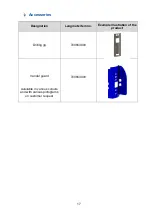
Page 17: ...7 Accessories Designation Langmatz item no Example illustration of the product Drilling jig 700663080 Vandal guard Available in various colours and with various pictograms on customer request 70066309...

Page 18: ...rmity for this product can be requested from Langmatz GmbH Measures Intervals Remarks External visual inspection At least every 12 months or during maintenance measures on the complete installation Ch...

Page 19: ...xperience any problems with it please contact our hotline see chapter 15 Contacts Quality management Langmatz GmbH s quality management system is certified to DIN EN ISO 9001 Disclaimer Warranty The i...

Page 20: ...20 12 524 0960 000 As of 18 11 2019 Original Operating Instructions...

Reviews: