OPERATING INSTRUCTIONS
3-21
Free Spool Clutch Operation (DP
Winch)
DP winches are equipped with either a manual or air
operated freespool clutch depending on the model.
1.
The manual freespool clutch is operated by pulling
lever kickout
Figure 3-10: Manual Lever Kickout
2.
The air freespool clutch is operated by application of
air pressure to the fitting supplied on the winch
gearbox housing
The fitting is
designed to accept 1/4” rigid plastic tubing.
a.
To release the clutch (freespool operation): Apply
60-400 psi air pressure to the air fitting.
b.
To engage the clutch (winch operation): Remove
all air pressure (0 psi) from the air fitting.
Figure 3-11: Air/Hydraulic Kickout
Free Spool Clutch Operation (Braden)
1.
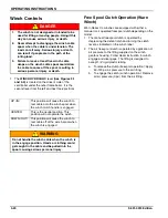
The WINCH CLUTCH HANDLE
and 3-13)
is located on the right or curb-side end of
the winch assembly.
The function of the winch clutch handle is to engage
or disengage the winch, allowing it to respond to the
Winch Hydraulic lever.
Figure 3-12: 12,000 Lb. Winch Clutch
Figure 3-13: 20,000 Lb. Winch Clutch
DISENGAGE
ENGAGE
dp manual
dp air-hyd
60-400 PSI
AIR PRESSURE
DISENGAGE
When the handle is placed in this
position, the winch is disengaged. This
allows the spool to “free-wheel” and the
winch is not affected by use of the
Winch Hydraulic lever.
ENGAGE
When the handle is placed in this
position, the winch is engaged and
cable may be spooled on or off the
winch spool. The winch can now be
controlled through the use of the Winch
Hydraulic lever.
ENGAGE
DISENGAGE
PULL
clutch12
ENGAGE
DISENGAGE
clutch20
Summary of Contents for 825D Series
Page 2: ......
Page 6: ...iv F 691 0913 Edition...
Page 14: ...2 6 F 691 0913 Edition STANDARD SPECIFICATIONS...
Page 40: ...3 26 F 691 0913 Edition OPERATING INSTRUCTIONS Page Intentionally Blank...
Page 60: ...4 20 F 691 0913 Edition MAINTENANCE AND LUBRICATION Figure 4 13 Axle and Brake Assembly...
Page 77: ...TROUBLESHOOTING GUIDE 5 9 Notes...
Page 78: ...5 10 F 691 0913 Edition TROUBLESHOOTING GUIDE...
Page 79: ......

