background image

Gyr

Chapter 2 - Installation

Installation and User Guide

 98-1178 Rev AA

13

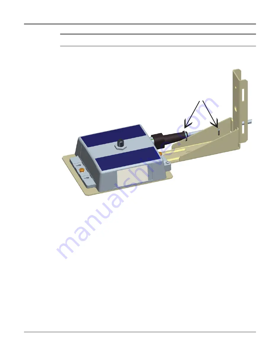
NOTE: Be sure to push the plug all the way in and feel a click to lock the AC cable.

3.

Insert and tighten two UV stable tie wraps (G) to attach the AC cable, while making sure the 
cable is straight and not twisted up or down relative to its mating connector.

Figure 2 - 3.  Tighten Cable Ties

G

DRAFT 

5.14.2012

Summary of Contents for Gridstream RF Series IV

Page 1: ...LANDIS GYR CONFIDENTIAL INFORMATION Landis Gyr Gridstream RF Series IV Mesh Extender Installation and User Guide Publication 98 1178 Rev AA D R A F T 5 1 4 2 0 1 2 ...

Page 2: ... publication or the information contained in it even if Landis Gyr has been advised knew or should have known of the possibility of such damages 2012 Landis Gyr Inc All Rights Reserved Landis Gyr Gridstream RF Series IV Mesh Extender Installation and User Guide Publication 98 1178 Rev AA Revision History Modification Date Revision Description Author 5 14 2012 AA Work in progress Kim Utesch Landis ...

Page 3: ...n Procedure 15 Metal Pole Mount Installation 18 Required Tools 18 Metal Pole Installation Procedure 18 Streetlight Arm Mount Installation 21 Mount Extender to Streetlight Bracket 21 Mount on Streetlight Arm 22 Grounding Optional 24 Chapter 3 RadioShop and Endpoint Testing Manager ETM 25 Configuration Using RadioShop 25 Wireless Configuration 25 Connect to Your Local Radio using RadioShop 25 Config...

Page 4: ...rt Installation File IIF Optional 30 Create an Import Installation File 31 Importing the IIF 32 Time Zone 33 Extender Management 34 Remove Extender from Command Center 38 Chapter 5 Product Specifications 41 Series IV Mesh Extender Specifications 41 Technical Support 42 How to Contact Us 42 Troubleshooting 42 D R A F T 5 1 4 2 0 1 2 ...

Page 5: ...ork in rural environments where the distance between neighboring endpoints is too great for them to communicate reliably Figure 1 1 Landis Gyr Gridstream RF Series IV Mesh Extender FCC and Industry Canada Compliance FCC Class B This device complies with Part 15 of the FCC rules Operation is subject to the following two condi tions 1 This device may not cause harmful interference and 2 This device ...

Page 6: ...ce exempt RSS standard s Operation is subject to the following two conditions 1 this device may not cause interference and 2 this device must accept any interference including interference that may cause undesired operation of the device Under Industry Canada regulations this radio transmitter may only operate using an antenna of a type and maximum or lesser gain approved for the transmitter by In...

Page 7: ...approuvé par Industrie Canada pour fonctionner avec les types d antenne énumérés ci dessous et ayant un gain admissible maximal et l impédance requise pour chaque type d antenne Les types d antenne non inclus dans cette liste ou dont le gain est supérieur au gain maximal indiqué sont strictement interdits pour l exploitation de l émetteur Référence 106119 000 Antenne fouet 5dBi 915MHz N Con 50 ohm...

Page 8: ...D R A F T 5 1 4 2 0 1 2 ...

Page 9: ...supervisory team assumes responsibility for ensuring that installers are properly trained authorized and continually qualified to perform their work The team must also take responsibility for the safety of their installers and to assure safe work methodologies Installers must understand that their supervisor s responsibility does not relieve them from their individual responsibility to perform the...

Page 10: ...Antenna The Extender requires an antenna to communicate with the endpoints and to relay information from the endpoint to the host application The antenna is mounted directly to the top of the Extender enclosure by means of an N type connector Only the authorized antenna provided with the Extender may be used The Extender may be orientated with the antenna either up or down to obtain the best commu...

Page 11: ... 4 SS 22 1160 2 Bracket Mounting Wood Pole Optional Sold Separately 22 1299 0 Bracket Streetlight Pole Mount 28 1312 1 V Bolt 20 Pole Mount 1 5 to 4 Pipe Diameter 28 1313 1 Cable Tie 5 6 inch Length UV Nylon Black 30 0055 2 Landis Gyr RF Mesh Extender Hardware Kit 45 1093 1 45 1093 Components Conn Ground Barrel Lug 1 4inch 16 1306 1 Screw 1 4 20 X 3 4 Phillips Pan Head SS 22 1146 3 Washer Spring L...

Page 12: ...t in the orientation as shown in Figure 2 1 Insert screw A with a spring washer B and a flat washer C in the center hole of each side of the Extender and align to the pem nuts in the mounting bracket D Figure 2 1 Attach Extender to the Mounting Bracket 2 Insert the plug of the AC cable E into the AC socket F Figure 2 2 Attach AC Cable A B C D E F D R A F T 5 1 4 2 0 1 2 ...

Page 13: ...to push the plug all the way in and feel a click to lock the AC cable 3 Insert and tighten two UV stable tie wraps G to attach the AC cable while making sure the cable is straight and not twisted up or down relative to its mating connector Figure 2 3 Tighten Cable Ties G D R A F T 5 1 4 2 0 1 2 ...

Page 14: ...hole in the enclosure D 3 Insert and tighten the screw E to fix the wire as shown 4 Tighten the set screw F on the ground connector Figure 2 4 Install Ground Connector Wood Pole Mount Installation Required Tools Installation sheet Extender applicable installation kit Extender power cable Extender antenna Optinal 6 AWG solid copper ground wire Personal protection equipment Power disconnect box Powe...

Page 15: ...he hole must be centered side to side on the pole Hole must be straight and level through the middle of pole 3 Hold the Extender and mounting bracket in place and insert 5 8 inch DA bolt through the center mounting bracket hole Place washers and nuts on both side of the pole Figure 2 5 Attach Mounting Bracket to Wood Pole NOTE The Extender may be mounted with either an Up or Down antenna orientati...

Page 16: ... some slack to rest below metal parts The slack is called a drip loop With a drip loop water from rain and condensation drips from the cable without damaging associated mechanical equipment 7 With the power disconnect switch in the OFF open position make the connection between the Extender power disconnect switch and power source according to local codes and best practices Installations where the ...

Page 17: ... tight seal at the base of the antenna The antenna should never be more than 10 off in any direction from being perpendicular to the ground Figure 2 7 Attach Antenna 9 Connect the grounding wire if required to the pole ground or neutral ground as local code allows If no ground wire is present install a 8 by 5 8 copper clad steel ground rod and connect with the proper clamp Attach the ground wire t...

Page 18: ...er antenna UV stable tie wraps 6 AWG solid copper ground wire optional Personal protection equipment Power disconnect box Adjustable end wrenches Standard socket wrench set Wire strippers Steel bands Steel banding tool Screwdrivers 6 AWG solid copper wire ground connector optional Miscellaneous hardware as required for installation and grounding Metal Pole Installation Procedure The following proc...

Page 19: ... switch and power source according to local codes and best practices Installations where the power cable is wired directly to the power source must be sealed with waterproofing compound to prevent water ingress into the power cable 7 Using UV stable tie wraps secure the power cable to the pole Landis Gyr recommends tie wraps that are 1 2 to 3 4 wide While securing the power cable to the pole care ...

Page 20: ... copper clad steel ground rod and connect with the proper clamp Attach the ground wire to the pole with the proper staples and standard spacing A Be sure to avoid right angle or sharp bends in routing the ground wire B Bond this ground wire to the power neutral if local rules require 10 Energize the Extender by moving the power disconnect to the ON closed position in the installed power disconnect...

Page 21: ...on hand and available 1 Attach the Extender to the streetlight mounting bracket A Insert bolt A with a spring washer B and a flat washer C in the center hole of each side of the Extender and align to the holes in the mounting bracket D B Tighten the screws with a torque of 45 in lb C Insert the connector of the AC power cable E into the AC power socket F Be sure to push the connector all the way d...

Page 22: ...e the cable is straight and not twisted up or down relative to its mating connector D Securely hand tighten the included antenna E on the antenna mounting connector of the Extender Figure 2 10 Mount to Streetlight Arm NOTE The antenna should never be more than 10 off in any direction from being perpendicular to the ground If the Extender is mounted upside down antenna up always inspect and verify ...

Page 23: ...t tie wraps be the steroid version about 1 2 to 3 4 wide and very thick While securing the power cable to the streetlight arm care must be taken to NOT DAMAGE the outer jacket of the power cable A nick in the outer jacket will allow water to migrate inside the Extender or the adapter Provide enough tension relief and a drip loop for the power cable Figure 2 11 Extender Mounted on Streetlight Arm D...

Page 24: ...re is recommended 1 Install a 6 AWG solid copper wire ground connector A by tightening the screw B 2 Insert the grounding wire C through the ground connector and into the small hole in the enclosure D 3 Insert and tighten the screw E to fix the wire as shown 4 Tighten the set screw F on the ground connector Figure 2 12 Attach Ground Wire D E A B F C D R A F T 5 1 4 2 0 1 2 ...

Page 25: ...lease refer to the latest RadioShop user s manual Connect to Your Local Radio using RadioShop Connect the LAN Packet Protocol port of your IWR to your computer s serial port using a serial cable Once the radio is powered up you can launch RadioShop on your computer RadioShop will now connect to your local head end radio IWR 1 Open RadioShop 2 From RadioShop home select the Head End Mgmt tab 3 Clic...

Page 26: ... ID the radio must be changed to match Configure Local Radio to Match the Extender Network ID To change the Network ID of the Local Radio perform the following steps NOTE All Landis Gyr Gridstream radios including the Extender ship with a default network ID or CRC of 670 In order to communicate with the new Extender your local radio will have to be reconfigured to match the network ID 670 of the E...

Page 27: ... Network ID has been assigned to the radio Click Finish to return to RadioShop Figure 3 6 Click Finish to Finalize Configuration 6 RadioShop will reboot your Local Radio and run another Radio Configuration Report 7 Make sure the Network ID of your Local Radio has changed If the Radio Configuration Report times out run another one Figure 3 7 Network ID is Now 670 Adding New Radios to RadioShop You ...

Page 28: ...Nodes Pane 5 Highlight the new Extender and click Reports Configuration Radio to verify that you can communicate with the Extender Locate your Extender using RadioShop The Extender must be connected to power for configuration 1 Click Generate WAN Nodes Report on the toolbar 2 Right Click your Local Radio and click Discover Neighbors 3 Click your Extender s LAN ID 4 Generate a Radio Configuration R...

Page 29: ...loaded into the Extender No GEO coordinates LAT LONG loaded into the Extender To complete the auto registration process a Meter Manufacturer File MMF must be imported into Command Center Importing Extenders into Command Center Meter Manufacturer File The Meter Manufacturer File provides Command Center with information on the Extender ID and the module serial number This file is not currently provi...

Page 30: ...Import Meter Manufacturer Data screen 2 Click the Browse button to navigate to and select the file that you just created 3 Click the Save button to import the file into the database The Meter Manufacturer Data Import Upload Complete window will appear displaying the Error Summary if applicable and Successful Entries Figure 4 2 Figure 4 2 Upload Complete Window 4 Successful entries will be added to...

Page 31: ...ds Table 4 1 Data Format Format Description User ID AlphaNum 30 Login assigned by the utility for the installer Utility may elect to use 1 for System usage Installation Date Date MM DD YYYY 12 26 2009 Actual date the meter was installed This date is used in various Command Center reports to track deployment statistics Installation Time TimeHHMMAM PM 11 12 AM Actual time the meter was installed Thi...

Page 32: ...n Figure 4 4 Import Installation File Window 2 Enter the path to the location of the Import Installation File created earlier or 3 Click the Browse button to navigate to the location of the desired file Installed Meter Number AlphaNum 20 Meter number of the new meter being installed This meter must exist in Command Center prior to importing the Import Installation File Must parse to Decimal format...

Page 33: ...ender that indicates the time zone in which the endpoint is installed and whether Daylight Savings Time DST is observed in the given time zone The meter installer should include the endpoint time zone in the Installation File To make it easy for installers to specify a time zone the Time Zone List link will open a document that displays a list of valid time zone designations by country 1 From Comm...

Page 34: ...creen summarizes information about a selected Extender and provides an interface for sending commands to the Extender Following is the procedure to view Gridstream RF Endpoint Information for a Extender from main Command Center screen 1 From Command Center home select Operations Endpoints The Endpoint Meter Selection window will open Figure 4 7 Endpoint Meter Selection 2 Enter the Extender Serial ...

Page 35: ...ender has most recently used for communication Select the Collector link to view the Collector screen Latitude Longitude Displays the latitude and longitude of the endpoint WAN Address Displays the mobile WAN address assigned to the Extender The following tabs are available General The General Settings screen displays the endpoint s current settings Manage The Manage screen allows the user to issu...

Page 36: ... progress of a new firmware download Pending Firmware Version Indicates the firmware version currently queued for download to the Extender Will be active on Indicates the date the pending firmware version will be downloaded to the Extender Grid Location Displays the Extender s grid location if applicable Pole Number Displays the Extender s pole number if applicable Meter Position Displays the Exte...

Page 37: ...mand will provide firmware and DCW versions Get WAN Node List The Get WAN Node List command response shown in Figure 4 10 displays the total number of devices communicating with this Extender and details of the top ten devices This provides useful information for determining how the Extender is functioning within the mesh Figure 4 10 Get WAN Nodes List command response Set WAN Address This command...

Page 38: ...ws the user to remove a deployed Extender from service The removed Extender can either be put back into inventory or archived 1 From Command Center select Operations Endpoints The Endpoint Meter Selection window will open 2 Enter the Extender serial number in the Endpoint field 3 Click GO The Available Tasks list will appear Figure 4 13 Endpoint Meter Selection Available Tasks 4 From the Available...

Page 39: ... Enter Removed Endpoint Information Select a reason for the removal from the drop down list box D Awaiting Redeployment This option will transition the endpoint to Inventory status E Permanently Remove From Service This option will archive the endpoint An endpoint in archived status will not be included in any Command Center reports 6 Click Save to save changes A message indicating the success or ...

Page 40: ...D R A F T 5 1 4 2 0 1 2 ...

Page 41: ...5 to 57 6 kHz depending on data rate Output Impedance 50 ohms Frequency Stability 40C 85C f0 3ppm Receiver Data Rates 9 6 19 2 38 4 115 2 kbps Frequency Stability 40C 85C f0 3ppm Receiver Sensitivity 9 6 kbps 110 dBm typ 107 dBm min 19 2 kbps 108 dBm typ 105 dBm min 38 4 kbps 105 dBm typ 102 dBm min 115 2 kbps 100 dBm typ 97 dBm min IIP3 915 30 dBm Adjacent Channel Rejection 35 dB Worst Case Image...

Page 42: ...Perform a visual inspection to determine if there are any indications of damage to the unit 2 Verify that AC power is being supplied to the unit If there is power then proceed to step 3 3 Try to connect with a locally connected IWR configured the same Network ID as the Extender If after 5 minutes the locally connected IWR does not acquire the Extender in its neighbors list the Extender should be r...

Reviews: