


Installation and adjustament manual
21/26
PROGRAMMATION
maximum.
E) IDLE ENRICHMENT: this parameter allows
modification of the fuel enrichment during idle
condition, and it can be modified by +/- 20 steps
maximum.
F) DISABLE/ENABLE ADAPTIVE LEARN: This
button is used to activate or deactivate the
ADAPTIVE LEARN STRATEGY.
G) RESET MODIFICATIONS: This button zeros all
the modifications that have been entered; that is, it
deletes both the changes performed by the Adaptive
Learn and the manual corrections performed as in (B).
H) ENTER CHANGES: It transmits all the entries of
the Adaptive Learn screen to the ECU.
5.7.4.1 Operational principles
During its operation, the LIS calculates a correction factor
to the mapped strategy by processing the signal from the
Lambda sensor. This is then actuated by the actuators.
This correction factor is called INTEGRATOR (paragraph
6.5.2). The LIS performs the above-mentioned operation
to adapt itself to the vehicle’s characteristics, i.e. mileage,
spark plug conditions, air filter, fuel chemical composition,
etc.
The LIS ECU calculates an average of the applied
correction factor (INTEGRATOR), subdivided by RPM
range. This is displayed in the screen ADAPTIVE LEARN
at the item AVERAGE DRIFT (C). See Fig. 5.9.
5.7.4.2 Automatic correction
The value AVERAGE DRIFT (C), see Fig. 5.9, is used by
the automatic Adaptive Learn to set up a correction factor
that can be seen in the cell CORRECTIVE STEPS
PERFORMED, at the AUTOMATIC line (B). The value
in the CORRECTIVE STEPS PERFORMED cell is
algebraically summed to the value programmed in the map.
5.7.4.3 Manual correction
The values in the AVERAGE DRIFT cells show by how
much the carburetion must be further corrected, in the
event that the corrections performed by the automatic
Adaptive Learn are not sufficient. To this end, it is possible
to enter the value of the AVERAGE DRIFT cells in the
cell CORRECTIVE STEPS PERFORMED, INSTALLER
line, in the appropriate RPM range.
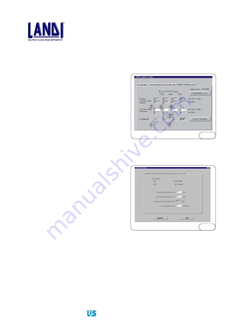
Example:
If a condition similar to the one in Fig. 5.10 occurs, the
AVERAGE DRIFT (1) value of the first range may be
inserted in the cell CORRECTIVE STEPS PERFORMED,
at the INSTALLER line (2); the same operation can be
performed for the 1,300 and 3,000 RPM range.
For the 3,000-5,300 RPM range, the Adaptive Learn has
already performed -2 corrective steps (3), since the
AVERAGE DRIFT (4) has exceeded the value of cell
MAXIMUM MODIFICATION STEPS PERFORMED,
at the AUTOMATIC (5) line. The possible manual
correction is to enter the value of -15 steps AVERAGE
DRIFT (4) in the cell (6) CORRECTIVE STEPS
PERFORMED.
The above description is just an example: the values and
the set-ups are solely to illustrate the procedure to be
followed in order to perform corrections.
5.7.5 CutOff
In this section, Fig.5.11 it is possible to choose the type of
cutoff and set the correct parameters to close the gas during
deceleration.
TYPE OF CUTOFF:
Fig.5.10
TOTAL: Selecting this parameter, the system work on
cutoff valve and close completely the passage of gas until
the number of RPM set on the cell “TOTAL CUTOFF
END”.
It is also possible to set in the apposite cell the “CUTOFF
ENGAGEMENT DELAY”.
PARTIAL: Selecting this parameter, the system work on
steps motors and close partial the passage of gas until the
number of RPM set on the cell “PARTIAL CUTOFF
END”. It is possible to choose on the apposite cell the per
cent “STEPPER-MOTOR OPENING IN PARTIAL
CUTOFF”.
It is also possible to set in the apposite cell the “CUTOFF
ENGAGEMENT DELAY”.
Fig. 5.11


