


LANDA SEHW • 8.913-932.0 • Rev. 02/12a
11
PRESSURE
W
ASHER
Tr
oub
leshooting Guide
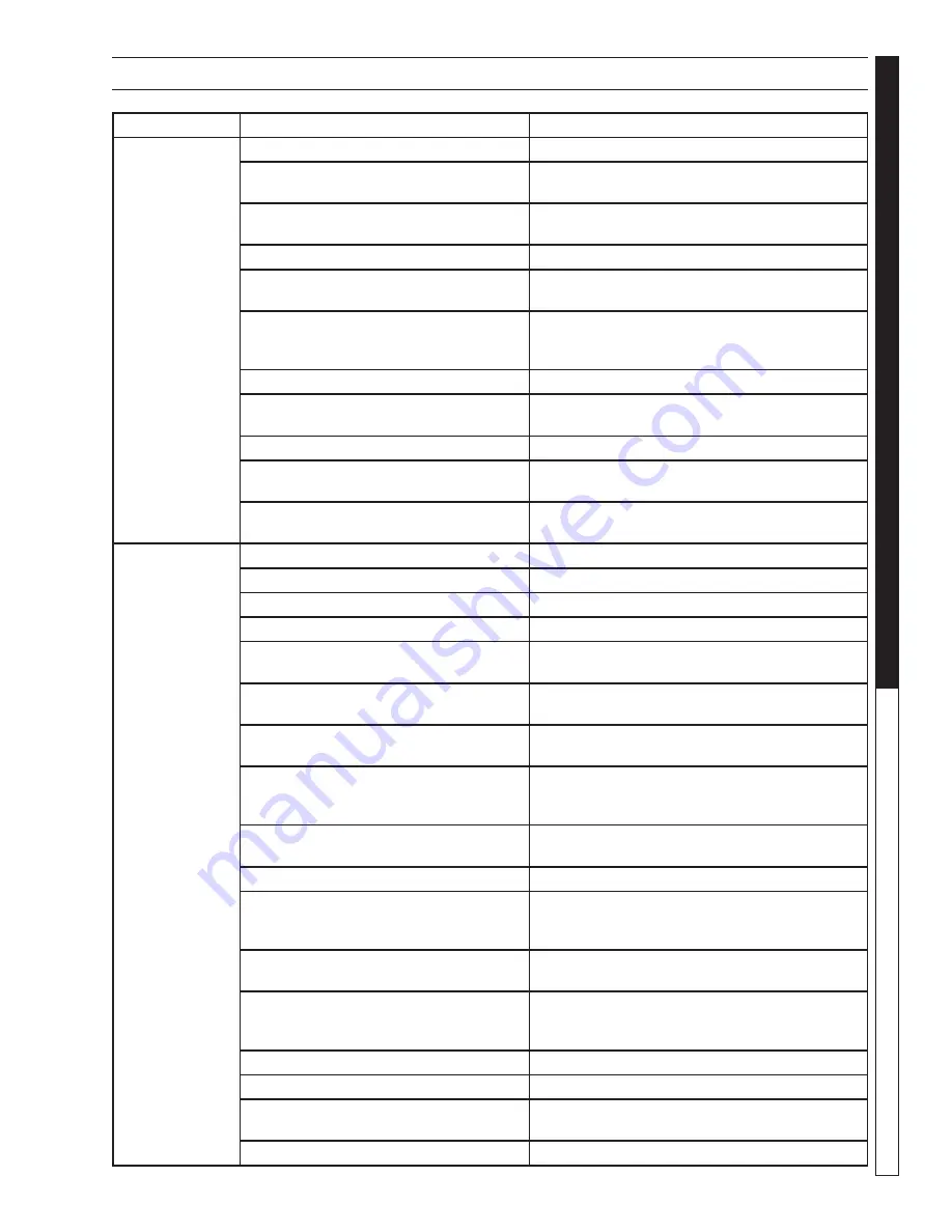
TROUBLESHOOTING
PROBLEM
POSSIBLE CAUSE
SOLUTION
LOW
OPERATING
PRESSURE
Faulty pressure gauge
Test with 2nd gauge. If bad install new gauge.
Insufficient water supply
Use larger garden hose; clean water filter at
inlet. Clean screen inside float tank.
Old, worn or incorrect spray nozzle
Match nozzle number to machine and/or
replace with new nozzle.
Belt slippage
Tighten or replace; use correct belt.
Plumbing or hose leak
Check plumbing system for leaks. Retape
leaks with teflon tape.
Faulty or mis-adjusted unloader valve
(Where applicable)
Adjust unloader for proper pressure. Install
repair kit when needed. Test PSI with unloader
removed, taking pressure directly off the pump.
Worn packing in pump
Install new packing kit.
Fouled or dirty inlet or discharge valves
in pump
Clean inlet and discharge valves.
Worn inlet or discharge valves
Replace with valve kit.
Low power supply
Check voltage of building and compare with
requirements. Obtain a different power source.
Detergent metering valve left open
sucking air, or faulty metering valve
Close and/or replace metering valve.
BURNER WILL
NOT LIGHT
Little or no fuel
Fill tank with fuel.
Improper fuel or water in fuel
Drain fuel tank and fill with proper fuel.
Plugged fuel filter
Replace as needed.
Misadjusted burner air bands
Readjust air bands for clean burn.
Little or no fuel pressure from fuel pump Increase fuel pressure to specification on fuel
pump and/or replace fuel pump.
Faulty burner transformer
Test transformer for proper arc between
contacts. Replace as needed.
Disconnected or short in electrical
wiring
All wire contacts should be clean and tight.
No breaks in wire.
Burner motor thermal protector tripped
If tripped, check voltage, connections, and
extensions for cause. Check fuel pump shaft
rotation for binding causing motor to overheat.
Flex-coupling slipping on fuel pump
shaft or burner motor shaft
Replace if needed.
On-Off switch defective
Check continuity through burner switch.
Heavy sooting on coil and burner, can
cause interruption of air flow and
shorting of electrodes
Clean as required.
Improper electrode setting
Clean and set according to
diagram in Operators Manual.
Fuel not reaching combustion chamber
Check fuel pump for proper flow. Check
solenoid flow switch on units with spray gun
control, for proper on-off fuel flow control.
Clogged burner nozzle
Replace.
Water not flowing through unloader
Open spray gun to allow water to flow.
Flow switch malfunction
Remove test for continuity and replace as
needed.
Fuel solenoid malfunction
Replace if needed
Summary of Contents for SEHW6-3500
Page 36: ......
Page 38: ...Form 8 913 932 0 Revised 02 12a Printed in U S A...