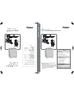
background image

12

Maintenance

Electrode Setting

Gun Setting Instructions

For EHASR Only

Periodically Check Wiring Connections. If Necessary

To Adjust Electrodes, Use Diagram.

Fuel Pressure Adjustment

To adjust fuel pressure, First install a pressure gage 

into the port just after the pump fuel exit. Turn the 

adjusting screw (located at the regulator port) 

clockwise to increase, and counterclockwise to 

decrease. Do not exceed 200 psi or lower the pressure 

below 130 PSI, when checked at the post-pump 

pressure port. 
The fuel pressure may need to be adjusted due to 

altitude. For every 500 ft altitude above sea level, the 

boiling point of water goes down 1 °F. At high altitude 

environments, this boiling point change may require the 

heat input to be lowered so the water input does not 

turn to steam earlier than at the factory settings and 

activate the pressure sensors and pressure relief 

equipment when the unit is operated and much higher 

altitudes from factory settings or local dealer site 

settings. Check with your dealer before making local 

site fuel pressure adjustments.
Also, as ambient temperature changes seasonally, the 

fuel temperature in the feed tank and air temperature 

inlet can impact fuel flow. In more extreme tempera

-

tures, this local-site adjustment may also require 

different fuel nozzles for fuel inlet temperatures that are 

at seasonal extremes (higher or lower) in locations 

where the temperature changes are beyond moderate 

temperatures of between 40°F and 90°F. Colder 

temperatures will make for a thicker flow and less fine a 

fuel spray while hotter temperatures will make for a 

thinner flow a more fine spray with the same nozzle. 

Consider alternate nozzle configurations from the 

baseline factory-supplied nozzle for operating in such 

temperature extremes if performance is not meeting 

needs with air band and fuel pressure settings alone.

NOTE:  When changing fuel pump, a by-pass plug 

must be installed in return line port or fuel pump will 

not prime.

Burner Nozzle

Keep tip free of surface deposits by wiping it with a 

clean, solvent-saturated cloth, being careful not to plug 

or enlarge nozzle. For maximum efficiency, replace 

nozzle each season.

Burner Air Adjustment

The oil burner on this machine is preset for operation at 

altitudes below 500 feet. If operated at higher altitudes, 

it may be necessary to adjust the air band for a #1 or #2 

smoke spot on the Bacharach scale.
To adjust, start machine and turn burner ON. Loosen 

two locking screws found on the air band and close air 

band until black smoke appears from burner exhaust 

vent. Note air band position. Next, slowly open the air 

band until white smoke just starts to appear. Turn air 

band halfway back to the previously noted position. 

Tighten locking screws.
For higher altitudes, the air band opening may need to 

be increased; for lower altitude, the .air band may need 

to be decreased.
For higher humidity, the air band opening may need to 

be increased; for lower relative humidity, the .air band 

may need to be decreased.
For higher ambient temperatures the air band opening 

may need to be increased; for lower ambient tempera

-

tures, the air band opening may need to be decreased.
Adjust to your operating location’s environment as-

needed for best smoke spot and performance 

compliant with local, state, and federal regulations.

NOTE: If a flue is installed, have a professional 

serviceman adjust your burner for a #1 or #2 smoke 

spot on the Bacharach scale.

For additional burner component information, see 

Burner Assembly Exploded View page. It is recom

-

mended that the oil burner be serviced yearly or as 

needed. Contact your local service center.

Surefire Burner Air Adjustment

To adjust, start machine and turn burner ON. Loosen 

two locking screws found on the air band and close air 

band until black smoke appears from burner exhaust 

vent. Note air band position. Next, slowly open the air 

band until white smoke just starts to appear. Turn air 

band halfway back to the previously noted position. 

Tighten locking screws.

Landa SDHW6-35824 E/M Operator’s Manual  8.913-958.0 - AC

Summary of Contents for SDHW Series

Page 1: ...Model Hot Water Skid Mounted Diesel Powered Diesel Oil Heated Operator s Manual Pressure Washer MODELS SDHW6 35824E M Black 1 110 516 0 SDHW6 35824E MT Tan 1 110 560 0 For the Landa Dealer nearest you...

Page 2: ...2 Landa SDHW6 35824 E M Operator s Manual 8 913 958 0 AC Machine Data Label...

Page 3: ...Coil 11 Rupture Disk 11 Fuel 11 Fuel Grade Type Comments 11 Fuel Control System 11 Electrode Setting 12 Burner Nozzle 12 Surefire Burner Air Adjustment 12 Coil Removal 13 Coil Reinstallation 13 Troubl...

Page 4: ...umes which can ignite causing property damage or severe injury AVERTISSEMENT Des liquides inflammables peuvent produire des vapeurs qui peuvent s enflammer causant ainsi des dommages la propri t ou de...

Page 5: ...ne safety instructions provided 16 Never run pump dry or leave spray gun closed longer than 5 minutes 17 To reduce the risk of injury close supervision is necessary when machine is used near children...

Page 6: ...discharge hose to spray gun using teflon tape on threads 5 Check oil level on sight glass on rear of pump Oil should be visible half way up sight glass SAE 10W 40 non detergent 6 Check engine oil 7 F...

Page 7: ...tion Tool Box Adjustable Thermostat Steam Valve Detergent Valve Engine Switch Fuel Cap Hose Reel Garden Hose Not Included High Pressure Nozzle Spray Wand Pillow Tank Spray Gun Water Connection Hose Va...

Page 8: ...steady stream of water flows out of the spray gun Burner will now light automatically 7 NOTE Do not start machine with burner switch on 8 To apply detergent place detergent pick up tube into a contain...

Page 9: ...off engine See winterizing procedure under Mainte nance and Service CAUTION Do not allow pump to run longer than 5 minutes without water Disconnect all hoses to allow water to drain With machine off o...

Page 10: ...adjustment of the unloader may be necessary to maintain correct pressure Winterizing Procedure Damage due to freezing is not covered by warranty Adhere to the following cold weather procedures whenev...

Page 11: ...ype for normal ambient operation No 1 Diesel Fuel DF1 Recommended fuel type for cold weather operation in ambients which would result in DF2 waxing No degradation in performance or engine component li...

Page 12: ...in return line port or fuel pump will not prime Burner Nozzle Keep tip free of surface deposits by wiping it with a clean solvent saturated cloth being careful not to plug or enlarge nozzle For maximu...

Page 13: ...tank to chassis 6 Disconnect 1 2 pipe nipples from inlet and discharge side of coil 7 Remove top tank wrap exposing insulation and coil and fold back insulation 8 Remove bolts that hold down coil to...

Page 14: ...ne Clean or replace Plugged fuel filter Replace as needed Misadjusted burner air bands Readjust air bands for clean burn Little or no fuel pressure from fuel pump Increase fuel pressure to specificati...

Page 15: ...TOR WILL NOT RUN Fuel pump seized Replace fuel pump Burner fan loose or misaligned Position correctly tighten set screws Defective control switch Replace switch Loose wire Check and replace or tighten...

Page 16: ...orn Check and replace if necessary High humidity in air Check and change oil twice as often WATER DRIPPING FROM UNDER PUMP Piston packing worn Check and replace if necessary O Ring plunger retainer wo...

Page 17: ...ore first use of your new Power Washer Change pump oil after first 50 hours and every year or 500 hours thereafter Pump oil SAE 10W 40 non foaming Engine Oil 15W 40 CD SE Engine Burner fuel Ultra low...

Page 18: ...enance to keep the machine and its components in good working condition They are listed in this general order Unloader Valves Winterizing Procedure Adjustable Thermostat Pump Cleaning of Coils Pressur...

Page 19: ...re washer Warning information should be emphasized and understood If the operator is not fluent in English the manufacturer s instructions and warnings shall be read to and discussed with the operator...

Page 20: ...20 Notes Landa SDHW6 35824 E M Operator s Manual 8 913 958 0 AC...

Page 21: ...21 Parts Parts LANDA SDHW MILITARY MODEL 1 110 516 0 1 110 560 0 Landa SDHW6 35824 E M Operator s Manual 8 913 958 0 AC...

Page 22: ...6 158 159 108 108 159 159 70 69 6 6 160 162 163 160 162 163 156 72 92 7 16 14 13 12 10 11 4 17 140 18 23 20 1 3 8 21 19 113 151 31 31 119 146 146 114 142 152 152 140 152 152 15 140 141 114 124 24 139...

Page 23: ...PAP E DE DET ERG ENT ST EA M VA LV E VAL VUL A DE VAP OR SOU PAP E DE VAP EUR WA TE R PR ES SU RE PRE SI N DE AGU A PRE SSIO N D EA U 1 Shut down unit 2 Open steam valve 3 Turn therm ostat to maxim u...

Page 24: ...1 4 STREET BRASS 19 8 757 195 0 1 NIPPLE 1 4 CLOSE BRASS 20 8 709 158 0 1 FILTER FUEL OIL H2O SEPARATOR 21 8 757 205 0 1 HOSE BARB 1 4 BARB X 1 4 M NPTF 90 22 6 390 126 0 4 CLAMP HOSE UNI 46 54 23 9...

Page 25: ...PECIFICATIONS PAGES 62 PUMP BELT SEE SPECIFICATIONS PAGES 63 PUMP PULLEY SEE SPECIFICATIONS PAGES 64 PUMP BUSHING SEE SPECIFICATIONS PAGES 65 8 757 509 0 1 ELBOW STEEL 1 2 SAE M X 3 8 NPTF M 66 9 802...

Page 26: ...3 8 757 241 0 1 PLUG 3 8 ALLEN COUNTER SUNK W TAG 104 8 757 967 0 1 TEE RUN BRASS 1 2 M JIC X 1 2 NPTF M 105 8 757 239 0 1 ELBOW 3 8 MPT x 1 2 FPT ST STEEL W TAG 106 9 196 012 0 1 SCREW 10 24 X 1 4 10...

Page 27: ...8 9 803 559 0 1 CLAMP SCREW 9 16 W 1 1 4 OD SS 149 8 753 395 0 1 CABLE BATTERY 24 BLACK NOT SHOWN 150 8 753 430 0 1 CABLE BATTERY 51 RED NOT SHOWN 151 8 754 911 0 1 CHECK VALVE 1 WAY 1 4 BARB 152 9 80...

Page 28: ...28 Control Panel 14 21 2 28 29 8 16 17 4 15 31 3 25 18 1 20 13 12 26 10 12 4 12 13 26 13 33 7 11 23 22 22 9 24 32 27 27 6 9 30 Landa SDHW6 35824 E M Operator s Manual 8 913 958 0 AC...

Page 29: ...INE 15 9 802 764 0 4 SCREW 10 32 X 3 4 16 9 802 447 0 6 67 CONDUIT THERMOSTAT TUBE 17 8 717 937 0 1 PANEL ELECTRONIC LDW 8 717 917 0 1 HARNESS WIRING LDW NOT SHOWN 18 8 758 692 0 1 LABEL LANDA SDHW CO...

Page 30: ...30 Float Tank 17 4 12 1 16 4 2 14 10 15 5 7 8 11 3 9 To Pump Outlet 13 3 6 2 2 3 2 2 Landa SDHW6 35824 E M Operator s Manual 8 913 958 0 AC...

Page 31: ...1 TANK PLASTIC UNIVERSAL FLOAT 6 8 757 342 0 1 ELBOW 1 2 STREET BRASS 7 9 802 822 0 1 SCREW 5 8 18 X 1 1 2 SS BUTTON SOCKET 8 9 802 263 0 125 ft TUBING 5 16 X 9 16 50 60 DURO RUBBER 9 9 802 824 0 1 WA...

Page 32: ...k Valve 8 902 459 0 8 902 460 0 8 902 461 0 8 902 462 0 2 3 1 7 5 4 6 For Detail See Hose Reel Assy 3 18 17 15 16 15 14 3 13 14 11 12 11 8 9 10 19 21 20 22 Landa SDHW6 35824 E M Operator s Manual 8 91...

Page 33: ...1 ELBOW 1 SLIP X FIPT PVC 80 90 10 8 706 439 0 1 NIPPLE 1 PVC 80 CLOSE 11 8 706 366 0 33 ft PIPE 1 PVC 80 12 8 707 359 0 1 VALVE 1 PVC 80 S X S 13 8 706 444 0 1 ADAPTER FEM 1 S X FT PVC 80 14 8 706 70...

Page 34: ...16 WASHER 3 8 9 8 925 141 0 2 HOSE 3 8 X 100 2W 6000PSI LAN SW X SO 10 8 707 182 0 2 COUPLER 3 8 FEMALE SCREW 11 8 757 655 0 1 ADAPTER STEEL 1 2 JIC X 3 8 NPTF M 12 8 757 508 0 1 ADAPTER STEEL 1 2 SAE...

Page 35: ...2 8 707 185 0 1 NIPPLE 3 8 3 8 707 182 0 1 COUPLER SCREW 4 8 751 234 0 1 GUN LANDA L1050 5000 PSI 10 4 GPM 5 8 711 297 0 1 LANCE SS 35 4 6 8 711 371 0 1 NOZZLE 2503 TWO SPRAY GUN 8 711 399 0 1 NOZZLE...

Page 36: ...36 Wayne Burner EHASR AC Series Landa SDHW6 35824 E M Operator s Manual 8 913 958 0 AC...

Page 37: ...NER INNER EHA SR 9 8 700 729 0 1 AIR BAND 8 HOLE OUTER EHA SR 10 13279 1 COUPLING A B PUMP 11 8 700 704 0 1 OIL LINE 6 12 8 756 290 0 1 FUEL PUMP WCS COMBO W SOLENOID 120V 13 8 700 692 0 2 GASKET E M...

Page 38: ...3 0 2BK90H 8 715 593 0 25 MM 9 802 403 0 BX39 2 9 802 418 0 ENGINE Size Type Model Part Pulley Pulley Part Bushing Bushing Part 24 HP KOHLER 6 35824 E M 8 753 906 0 3TB40 9 802 394 0 P2X1 1 2 9 802 40...

Page 39: ...39 Landa SDHW6 35824 E M Operator s Manual 8 913 958 0 AC Specifications Wayne Burner Specifications Model Burner Fuel Nozzle w 100 PSI Check Valve SDHW6 35824E M 8 756 413 0 8 756 697 0...

Page 40: ...8 913 958 0 Printed in U S A...

Reviews: