8.917-208.0 • HOT Operator Manual • Rev. 03/12
PRESSURE
W
ASHER
T
roub
leshooting Guide
18
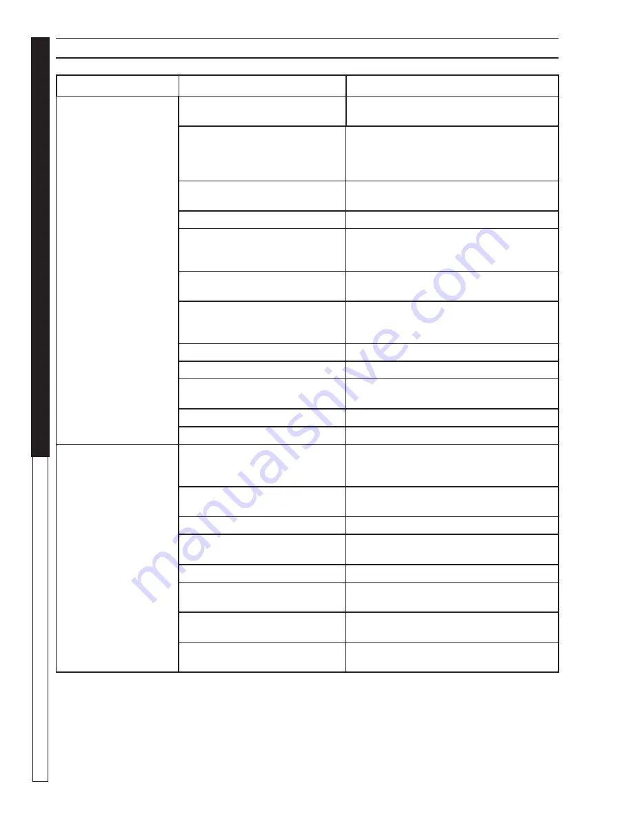
TROUBLESHOOTING
PROBLEM
POSSIBLE CAUSE
SOLUTION
BURNER LIGHT WILL
NOT LIGHT
Disconnected or short in electrical
wiring
All wire contacts should be clean and tight.
No breaks in wire.
Burner motor thermal protector
tripped
If tripped, check voltage, connections, and
extensions for cause. Check fuel pump shaft
rotation for binding causing motor to over-
heat.
Flex-coupling slipping on fuel
pump shaft or burner motor shaft
Replace if needed.
ON-OFF Switch defective
Check continuity through burner switch.
Heavy sooting on coil and burner,
can cause interruption of air fl ow
and shorting of electrodes
Clean as required.
Improper electrode setting
Clean and test according to diagram in Op-
erators Manual.
Fuel not reaching combustion
chamber
Check fuel pump for proper fl ow. Check sole-
noid fl ow switch on machines with spray gun
control, for proper on-off fuel fl ow control.
Clogged burner nozzle
Replace.
Water not turned on
Turn on water to activate burner fl ow switch.
Fuel solenoid malfunction
Remove, test for continuity and replace as
needed.
Fuel solenoid malfunction
Replace if needed.
Pressure switch malfunction
Test for proper operation. Replace if needed.
PUMP MOTOR STOPS
AFTER A FEW
MINUTES OF
OPERATION OR
STARTS SLOW
Insuffi cient voltage
Use heavier drop cord and check voltage at
receptacle. Check name plate for amperage
draw.
Plugged nozzle
Remove and clean nozzle. Turn on water
pump, fl ush lines, and replace nozzle.
Wrong spray nozzle
See serial plate for minimum nozzle size.
Automatic overload switch tripped
Allow motor to cool - then push Red reset
button.
Motor wet
Allow to dry.
Short in electrical wiring
Wire contacts should be clean and tight. No
breaks in wires.
Coil liming up causing excessive
pressure
See section on Preventative Maintenance.
Water pump low or out of oil caus-
ing the pump to bind up
Fill to correct level.