background image

8.917-208.0  •  HOT Operator Manual •  Rev. 03/12

13


PRESSURE W

ASHER


OPERA

T

OR’S MAN 

AL


MAINTENANCE & SERVICE

Step 3

  Attach a short section (3-5 ft.) of garden hose 

to machine to siphon solution from an el e vat ed 
con tain er. Turn machine on, allowing solution 
to be pumped through coils back into the con -
tain er. So lu tion should be allowed to circulate 
2-4 hours.

Step 4 

After circulating solution fl ush entire system with 
fresh water. Reinstall high pressure noz zle into 
wand.

Rupture Disk

If pressure from pump or thermal expansion should 
ex ceed safe limits, the rupture disk will burst, allow-
ing high pressure to be discharged through hose 
to ground. When the disk ruptures it will need to be 
replaced. Torque the re place ment rupture disk to 35 
foot pounds.

Fuel

Use clean fuel oil that is not contaminated with water 
and debris. Replace fuel fi lter and drain tank every 
100 hours of operation. Use No. 1 or No. 2 Heating 
Oil (ASTM D306) only. 

NEV ER 

use gasoline in your 

burn er tank. Gas o line is more com bus ti ble than fuel 
oil and could re sult in a se ri ous ex plo sion. 

NEVER


use crank case or waste oil in your burn er. Fuel unit 
mal func tion could re sult from con tam i na tion. 

Biodiesel fuels are becoming more popular as alter-
native fuels under the Green Initiative. Landa en-
dores the use of fuels that are blended with biodies-
els meeting ASTM D6751 and petroleum 
fuels meeting ASTM D396. Landa offers no 
opinion regarding the combustion characteristics 
of B5 blends. B5 biodiesel fuels are 5% ASTM 
D6751 biodiesel and 95% ASTM D396 fuel oil blend.
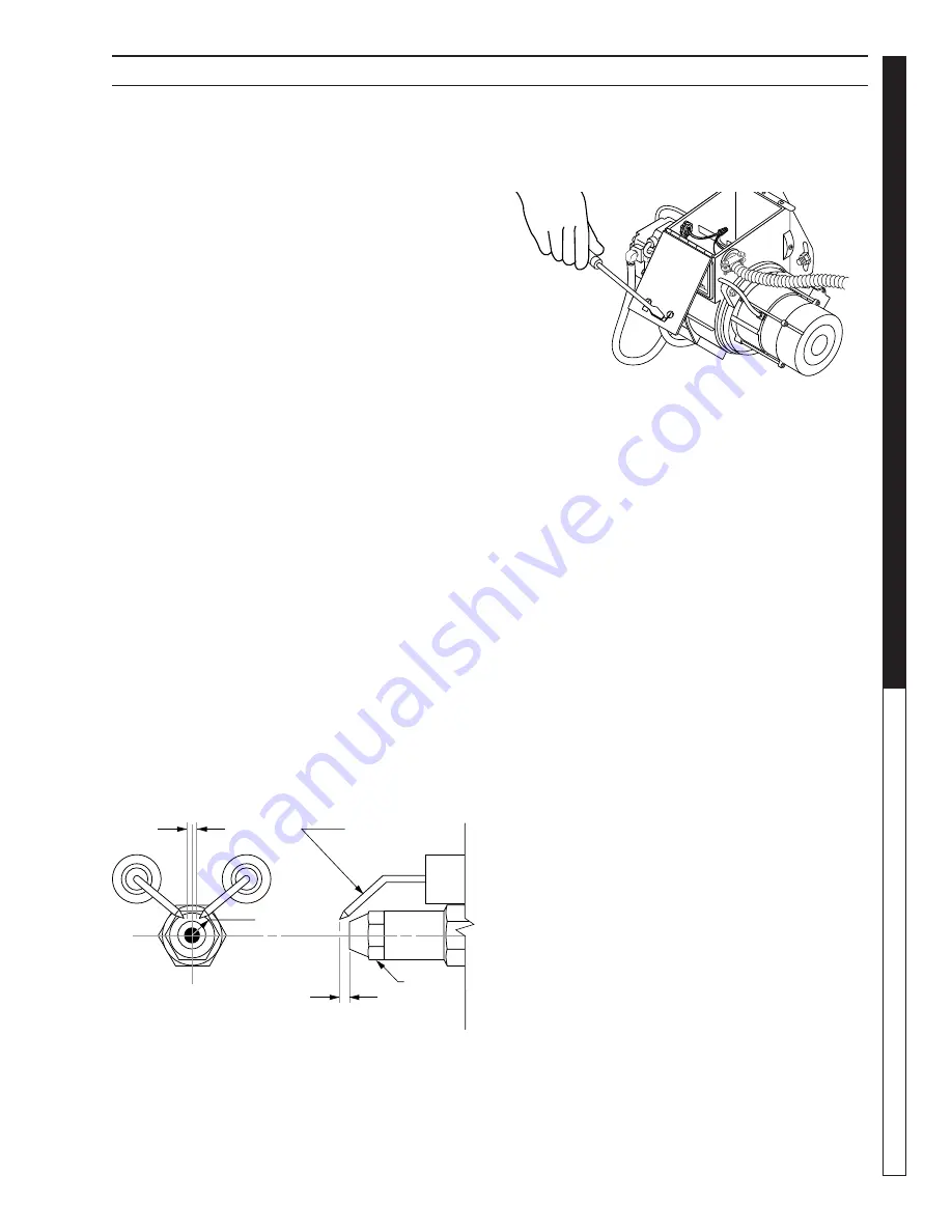
Electrode Setting

(See illustration below.)

Ignition Circuit

Pe ri od i cal ly inspect wires, spring contact and elec-
 trodes for condition, security and proper spacing. 
Trans form er test: 

(CAU TION 10,000 VOLTS)

 use 

defect free in su lat ed screw driv er and keep fi ngers 

Side View

Top View

1/16"

7/16"

5/32" Gap

Electrode

Nozzle

off blade! Lay blade across one contact: OK if arc 
will span 1/2" between end of blade and other 
contact (see illustration below).

Transformer Check

Burner Nozzle

Keep the tip free of sur face de pos its by wip ing it with 
a clean, sol vent-sat u rat ed cloth, being care ful not to 
plug or en large the nozzle. For max i mum ef fi  

cien cy, 

re place the nozzle each sea son.

Fuel Control System

These machines utilize a fuel solenoid valve located 
on the fuel pump to control the fl ow of fuel to the 
com bus tion chamber. This solenoid, which is nor-
mally closed, is ac ti vat ed by the unloader's pressure 
switch. When an op er a tor re leas es the trigger on the 
spray gun, the un load er goes into a by-pass mode, 
thus stop ping elec tri cal cur rent to the fuel solenoid 
coil. With the solenoid closed, the fuel supply to the 
combustion cham ber ceas es. Pe ri od ic in spec tion to 
insure that the fuel so le noid valve func tions properly 
is rec om mend ed. This can be done by op er at ing the 
machine and check ing to see that when the spray 
gun is in the OFF po si tion the burn er is not fi ring.

Fuel Pressure Adjustment:

To ad just fuel pres sure, turn the ad just ing screw 
(lo cat ed at the reg u la tor port) clock wise to in crease, 
coun ter clock wise to decrease. Do not exceed 200 psi.

NOTE:

 When chang ing fuel pump, a by-pass plug 

must be in stalled in return line port or fuel pump 
will not prime.

Beckett Burner Air Adjustment

The oil burner on this machine is preset for opera-
tion altitudes below 1000 feet. If operated at higher 
altitudes, it may be necessary to adjust the air band 
setting. Adjust air band for a #1 or #2  smoke spot 
on the Bacharach scale.

If a smoky or eye-burn ing ex haust is being emit ted 
from the stack, two things should be checked. First, 
check the fuel to be cer tain that ker o sene or No. 1 
home heating fuel is be ing used. Next, check the air 
ad just ment on the burn er. An oily, black, smoky fi re 
indicates a lack of air and the air band should be 

Summary of Contents for HOT 3-300

Page 1: ...8 917 208 0 OPERATOR S MANUAL For technical assistance or the Landa Dealer nearest you consult our web page at www landa com HOT HOT 2 1100 HOT2 1500 HOT 4 2000 HOT 3 1100 HOT 3 300 89172080 1...

Page 2: ...th serial number and date of purchase and keep in a safe place for future reference 8 917 208 0 HOT Operator Manual Rev 03 12 Introduction Important Safety Information 4 5 7 Component Identification 6...

Page 3: ...ound fault circuit interrupter GFCI If rated more than 250 volts or more than single phase this product should only be connected to a power supply receptacle protected by a GFCI DANGER Improper connec...

Page 4: ...pos sibility of a fall due to slippery surfaces 20 Do not overreach or stand on unstable support Keep good footing and balance at all times 21 Do not operate this machine when fatigued or under the i...

Page 5: ...zzle Detergent Pick up Tube Quick Coupler Power Supply GFCI Steam Nozzle Steam Wand 3 300 Spray Gun Trigger Variable Pressure Control Handle Variable Pressure Wand 2 11024D 2 15024D 3 11024D 4 2000 Pu...

Page 6: ...fresh air may have to be piped to the burner and a fan installed bringing the air into the machine WARNING Avoid small areas or areas near exhaust fans Electrical The machine when installed must be e...

Page 7: ...hreads Move safety latch into locked position STEP 6 Check oil level by using supplied dip stick Use SAE 30W non detergent only STEP 7 Fill fuel tank with proper fuel 89172080 9 STEP 5 Release the cou...

Page 8: ...en turn the vari able pressure control handle coun terclockwise to reduce pressure 89172080 13 Selection of high or low pressure is accompanied by turning the handle Note High pressure nozzle must be...

Page 9: ...rectly into cleaning solu tion and apply to surface at low pressure for best results limit your work area to sections approxi mately 6 feet square and always apply detergent from bottom to top Allow d...

Page 10: ...hat position This closes both the intake and exhaust valves to prevent rusting of cylinder 4 Cover the pressure washer and store in a clean dry place that is well ventilated away from open flame or sp...

Page 11: ...s warranty Winterizing Procedure Damage due to freezing is not covered by warranty Adhere to the following cold weather procedures whenever the washer must be stored or operated outdoors under freezi...

Page 12: ...keep fingers Side View Top View 1 16 7 16 5 32 Gap Electrode Nozzle off blade Lay blade across one contact OK if arc will span 1 2 between end of blade and other contact see illustration below Transfo...

Page 13: ...locking screws found on the air band and close air band until black smoke appears from burner exhaust vent Note air band position Next slowly open the air band until white smoke just starts to appear...

Page 14: ...washer Perform maintenance more often under severe conditions Date Oil Changed Month Day Year Estimated Operating Hours Since Last Oil Change Date Oil Changed Month Day Year Estimated Operating Hours...

Page 15: ...igh limit switch Replace Insufficient water supplied Check water G P M to machine Restricted water flow Check nozzle for proper size or obstruc tion DETERGENT NOT DRAWING Air leak Tighten all clamps C...

Page 16: ...inlet water pressure Do not close trigger on spray gun for longer than 1 2 minutes OIL DRIPPINGS Oil seal worn Check and replace if necessary MACHINE SMOKES Improper fuel or water in fuel Drain tank a...

Page 17: ...ole noid flow switch on machines with spray gun control for proper on off fuel flow control Clogged burner nozzle Replace Water not turned on Turn on water to activate burner flow switch Fuel solenoid...

Page 18: ...ply 5 Normal maintenance service including adjustments fuel system cleaning and clearing of obstructions 6 Transportation to service center field labor charges or freight damage WHAT YOU MUST DO TO OB...

Page 19: ...Form 8 917 208 0 Revised 03 12 Printed in U S A...

Reviews: