background image

8.917-208.0  •  HOT Operator Manual •  Rev. 03/12

OPERA

T

OR’S MANU

AL


PRESSURE W

ASHER 


14

moved to allow the air to fl ow through the burner. 
Sharp eye-burn ing white fumes indicate too much 
air fl owing through the com bus tion chamber. The 
air band should be moved to al low less air to fl ow 
through the burn er.
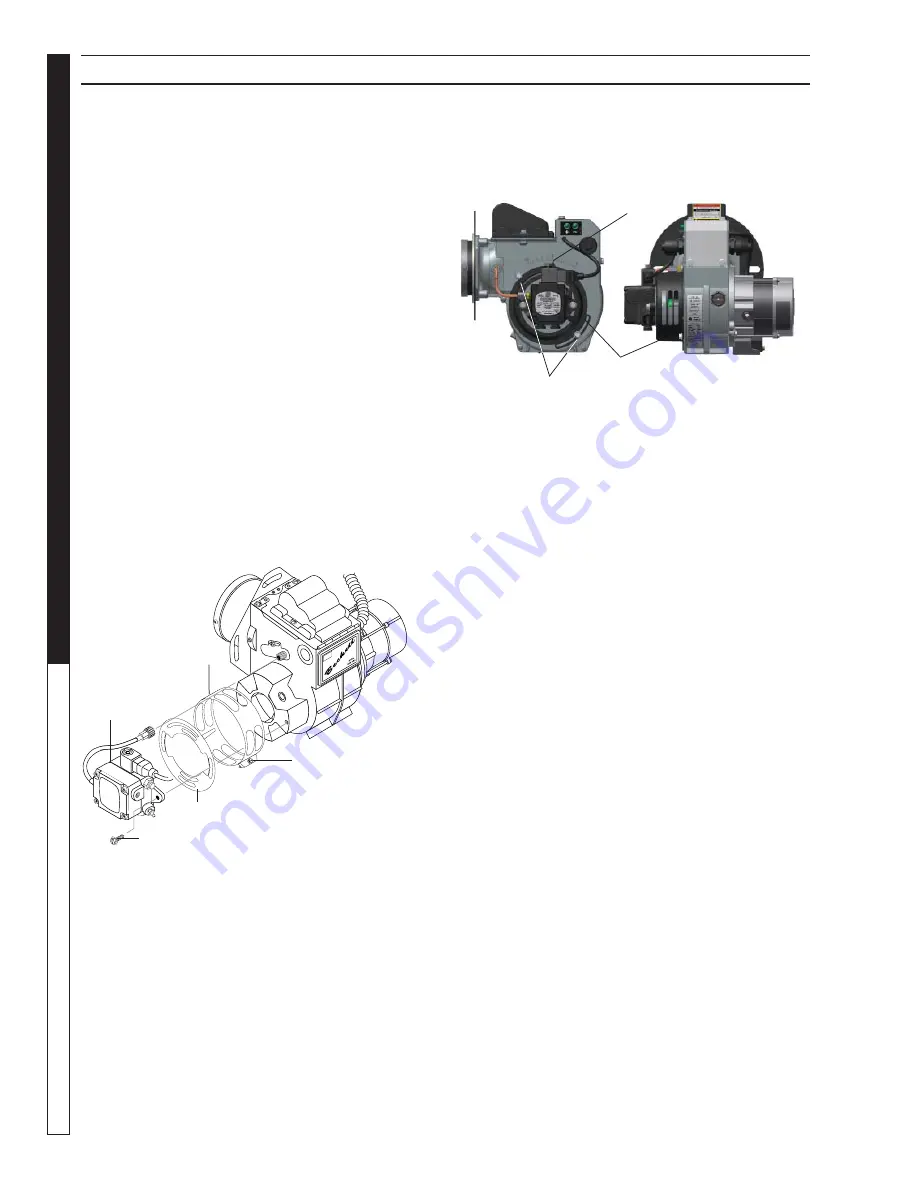
To Adjust:

 Start machine and turn burner ON. 

Loosen two locking screws found in the air shutter 
openings (re fer to illustration) and close air shutter 
until black smoke ap pears from burner exhaust vent.  
Note air band po si tion. Next, slow ly open the air 
shutter until white smoke just starts to appear. Turn 
air shutter halfway back to the black smoke position 
previously noted. Tight en lock ing screws.

If the desired position cannot be obtained using 
only the air shutter, lock the air shutter in as close a 
position as can be obtained, then repeat the above 
procedure on the air band setting.

Initial Air Adjustments:

 Allow suffi cient air to obtain 

a clean burning fl ame by loosening the lock screws 
and moving the air shutter and if necessary the bulk 
air band.

Reduce the air supply until the fl ame tips appear 
slight ly smoky, then increase the air just enough to 
cause the fl ame tips to appear absolutely clean.

Landa Sure Fire Oil Burner

Burner Air Adjustment:

 The oil burner on this 

machine is preset for operation at altitudes below 
1000 feet. If operated at higher altitudes, it may 
be necessary to adjust the air band for a #1 or #2 
smoke spot on the bacharach scale.

To adjust, start machine and turn burner ON. Loosen 
two locking screws found on the air band and close 
air band until black smoke appears from burner 

exhaust vent. Note air band position. Next, slowly 
open the air band until white smoke just starts to 
appear. Turn air band halfway back to the previously 
noted position. Tighten locking screws.

CAUTION: If white smoke appears from burner 
exhaust vent during start-up or operation, 
discontinue use and readjust air bands.

NOTE: If a fl ue is installed, have a professional 
serviceman adjust your burner for a #1 or #2 

smoke spot on the Bacharach scale.

Removal of Soot and Heating Coil

In the heating process, fuel residue in the form of 
soot deposits may develop between the heat ing 
coil pipe and block air fl ow which will affect burner 
combustion. When soot has been de tect ed on visual 
observation, the soot on the coil must be washed off. 
Follow these steps to re move the coil.

  1. Disconnect hose from pump to inlet side of the coil.

  2. Disconnect electrical connection to the ther mo stat.

  3. Remove quick coupler from inlet and discharge side 

of coil.

  4. Re move bur n er as sem bly from combustion 

cham ber.

  5. Re move the 3-3/8" bolts from each side of coil and 

tank as sem bly (these bolts are used to fasten tank 
and handles to chassis).

  6. Dis con nect 1/2" pipe nipples from inlet and dis charge 

side of coil.

  7. Re move top tank wrap exposing in su la tion and coil 

and fold back in su la tion.

  8. Re move bolts that hold down coil to bot tom wrap.

  9. Re move coil.

 10. Replace or repair any insulation found to be torn or 

broken.

Coil Reinstallation

Reinstall new or cleaned coil by reversing Steps 9 
through 1 above. 

MAINTENANCE & SERVICE

Air 

Band

Beckett

Fuel 

Pump

Air Adjustment 

Screw

Air Shutter

Locking Screws

Reference Numbers

Air Band Locking Screws

Air Band

Summary of Contents for HOT 3-300

Page 1: ...8 917 208 0 OPERATOR S MANUAL For technical assistance or the Landa Dealer nearest you consult our web page at www landa com HOT HOT 2 1100 HOT2 1500 HOT 4 2000 HOT 3 1100 HOT 3 300 89172080 1...

Page 2: ...th serial number and date of purchase and keep in a safe place for future reference 8 917 208 0 HOT Operator Manual Rev 03 12 Introduction Important Safety Information 4 5 7 Component Identification 6...

Page 3: ...ound fault circuit interrupter GFCI If rated more than 250 volts or more than single phase this product should only be connected to a power supply receptacle protected by a GFCI DANGER Improper connec...

Page 4: ...pos sibility of a fall due to slippery surfaces 20 Do not overreach or stand on unstable support Keep good footing and balance at all times 21 Do not operate this machine when fatigued or under the i...

Page 5: ...zzle Detergent Pick up Tube Quick Coupler Power Supply GFCI Steam Nozzle Steam Wand 3 300 Spray Gun Trigger Variable Pressure Control Handle Variable Pressure Wand 2 11024D 2 15024D 3 11024D 4 2000 Pu...

Page 6: ...fresh air may have to be piped to the burner and a fan installed bringing the air into the machine WARNING Avoid small areas or areas near exhaust fans Electrical The machine when installed must be e...

Page 7: ...hreads Move safety latch into locked position STEP 6 Check oil level by using supplied dip stick Use SAE 30W non detergent only STEP 7 Fill fuel tank with proper fuel 89172080 9 STEP 5 Release the cou...

Page 8: ...en turn the vari able pressure control handle coun terclockwise to reduce pressure 89172080 13 Selection of high or low pressure is accompanied by turning the handle Note High pressure nozzle must be...

Page 9: ...rectly into cleaning solu tion and apply to surface at low pressure for best results limit your work area to sections approxi mately 6 feet square and always apply detergent from bottom to top Allow d...

Page 10: ...hat position This closes both the intake and exhaust valves to prevent rusting of cylinder 4 Cover the pressure washer and store in a clean dry place that is well ventilated away from open flame or sp...

Page 11: ...s warranty Winterizing Procedure Damage due to freezing is not covered by warranty Adhere to the following cold weather procedures whenever the washer must be stored or operated outdoors under freezi...

Page 12: ...keep fingers Side View Top View 1 16 7 16 5 32 Gap Electrode Nozzle off blade Lay blade across one contact OK if arc will span 1 2 between end of blade and other contact see illustration below Transfo...

Page 13: ...locking screws found on the air band and close air band until black smoke appears from burner exhaust vent Note air band position Next slowly open the air band until white smoke just starts to appear...

Page 14: ...washer Perform maintenance more often under severe conditions Date Oil Changed Month Day Year Estimated Operating Hours Since Last Oil Change Date Oil Changed Month Day Year Estimated Operating Hours...

Page 15: ...igh limit switch Replace Insufficient water supplied Check water G P M to machine Restricted water flow Check nozzle for proper size or obstruc tion DETERGENT NOT DRAWING Air leak Tighten all clamps C...

Page 16: ...inlet water pressure Do not close trigger on spray gun for longer than 1 2 minutes OIL DRIPPINGS Oil seal worn Check and replace if necessary MACHINE SMOKES Improper fuel or water in fuel Drain tank a...

Page 17: ...ole noid flow switch on machines with spray gun control for proper on off fuel flow control Clogged burner nozzle Replace Water not turned on Turn on water to activate burner flow switch Fuel solenoid...

Page 18: ...ply 5 Normal maintenance service including adjustments fuel system cleaning and clearing of obstructions 6 Transportation to service center field labor charges or freight damage WHAT YOU MUST DO TO OB...

Page 19: ...Form 8 917 208 0 Revised 03 12 Printed in U S A...

Reviews: