31
Section 1: Assembly & Set-Up
RCF3696, RCFM3696, RCF3610, & RCFM3610 Rotary Cutters 326-600M
8/20/21
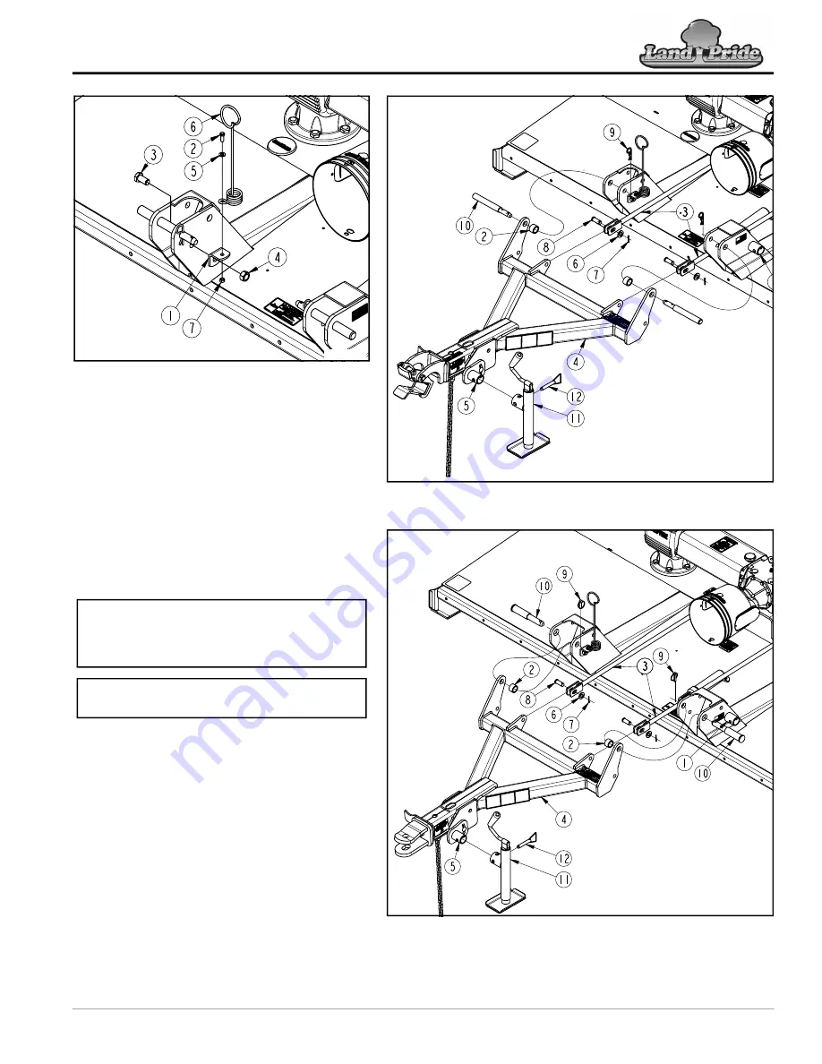
RCF(M)3696 Tongue Assembly
Figure 1-23
RCF(M)3610 Tongue Assembly
Figure 1-24
33945
35009
Spring Hose Loop Assembly
Figure 1-22
Spring Hose Loop (Pull-Type)
Refer to Figure 1-22:
1. Attach mounting bracket (#1) with
3/4"-10 x 1 1/2" GR5 cap screw (#3) and
locknut (#4) to the right-hand clevis as shown.
Tighten nut to the correct torque.
2. Attach spring hose loop (#6) to mounting
bracket (#1) with 3/8"-16 x 1" GR5 cap
screw (#2), flat washer (#5), and locknut (#4).
Tighten nut to the correct torque.
Tongue Assembly (Pull-Type)
Refer to Figure 1-23 for RCF(M)3696 and
Figure 1-24 for RCF(M)3610 cutters:
1. Assemble tongue (#4) to the deck with
hitch pins (#10), spacer tubes (#2), and
linchpins (#9) as shown.
2. Attach level rods (#3) to tongue (#4) with clevis
pins (#8), flat washers (#6), and cotter
pins (#7).
Park Jack Assembly (Pull-Type)
1. Remove park jack (#11) from storage mount
(#1) and attach to adjustable jack mount (#5)
with ball detent pin (#12). Make sure detent
pin is fully inserted.
2. Adjust park jack to be vertical. Refer to
35006
NOTE:
If preferred, the front guards may be
assembled first. See
“Assembly of Optional
Equipment”
on page 36 for front guard
assembly instructions.
NOTE:
Do not tighten hardware to the correct
torque until assembly is complete.


