Section 1: Assembly & Set-up
RC5610, RC6610, RCM5610, & RCM6610 Series 2 S/N Rotary Cutters 330-539M
5/6/20
26
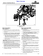
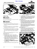
Lift Cylinder Mount Position
Refer to Figure 1-22:
Lift cylinder (#1) should be mounted in lower hole (A) if
cutter is equipped with 21" laminated tires or middle
hole (B) if cutter is supplied with 25.5" aircraft tires, or
upper hole (C) if 29" aircraft tires. Reposition lift cylinder
if it is not assembled in the correct hole.
1. Park tractor and cutter on a level surface and raise
center deck fully up.
2. Without lowering cutter, shut tractor down properly
before dismounting. Refer to
3. Place sturdy support blocks or jack stands under the
four corners of the center deck.
4. Remove all stroke control spacers (#4) from the
cylinder rod.
5. Start tractor and lower center deck onto the support
blocks until hydraulic cylinder hitch pin (#2) is loose.
6. Shut tractor down properly before dismounting.
7.
Remove hairpin cotter (#3) and hitch pin (#2).
8. Reposition hydraulic cylinder to the correct mounting
hole (A, B, or C) and reinsert hitch pin (#2). Secure
hitch pin with hairpin cotter (#3).
9. Start tractor, raise deck fully up, and properly shut
tractor down again before dismounting.
10. Replace stroke control spacers (#4) and remove
support blocks.
11. Start tractor and cycle hydraulic system by raising
and lowering center deck cylinder and wing folding
cylinders.
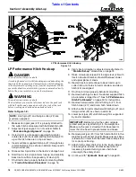
Adjust Light Kit
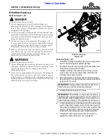
Refer to Figure 1-23:
The Light Kit will need to be adjusted when purchased
assembled to the cutter at the factory.
Adjust light kit as follows:
1. Shut tractor down properly before dismounting. Refer
to
2. On the right-hand wing, loosen hex locknuts (#1). Do
not remove locknuts.
3. Slide light assembly (#2) and mounting clamp (#3) as
far as possible toward the rod end of hydraulic
cylinder (#4).
4. Tighten each locknut (#1) one-half turn in a criss-
cross pattern until all nuts are tightened to the correct
torque.
Lift Cylinder Mount Position
Figure 1-22
Adjust Light Kit
Figure 1-23
Hook-up LED Lights
Refer to Figure 1-25 on page 27:
The lead wiring harness (#13) is equipped with a 7-way
round pin connector for connecting to the tractor’s 7-pin
electrical outlet shown in Figure 1-26 on page 27.
1. Route lead wire harness (#13) through spring hose
loops (#10).
2. Connect lead wire harness (#13) to the tractor’s
7-way round pin receiver.
3. It is best to have a second person verify the lights are
operating. Start tractor and operate lights as follows:
a. Turn on head lights to verify red lights illuminate.
b. Turn on flasher lights to verify amber light are
blinking on and off.
4. If the lights did not operate properly, recheck hook-up
of enhance module and wire harnesses. Make
necessary changes and repeat step 3 above.
5. Check wire harness routing to make sure wires will
not be pinched as the wing is folded and unfolded
and while raising and lowering cutter height.
6. Add cable ties to wire harness as needed to secure
the harnesses in place.
37840
37658a


