


Section 5: Maintenance & Lubrication
RC5610, RC6610, RCM5610, & RCM6610 Series 2 S/N Rotary Cutters 330-539M
5/6/20
47
10. Both blades should be sharpened at the same angle
as the original cutting edge and must be replaced or
re-ground at the same time to maintain proper
balance in the cutting unit. The following precautions
should be taken when sharpening blades:
a. Do not remove more material than necessary.
b. Do not heat and pound out a cutting edge.
c. Do not grind blades to a razor edge. Leave a blunt
cutting edge approximately 1/16" thick.
d. Always grind cutting edge so end of blade remains
square to cutting edge and not rounded.
e. Do not sharpen back side of blade.
f. Both blade s should weigh the same with not more
than 1 1/2 oz. difference. Unbalanced blades will
cause excessive vibration which can damage
gearbox bearings and create structural cracks.
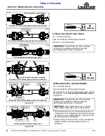
Refer to Figure 5-9 & Figure 5-10:
11. Carefully check cutting edges of blades in relation to
blade carrier rotation to ensure correct blade
placement. Cutter blades must be installed with
cutting edge leading in rotation
.
Refer to Figure 5-8 on page 46:
WARNING
!
To avoid serious injury or death:
A locknut that has been removed can lose its thread locking
properties. Reusing a used locknut can result in a thrown
blade. Always use a new locknut when installing blades.
IMPORTANT:
Examine blade bolts and their flat
washers for excessive wear and replace if worn.
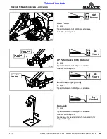
12. Insert blade bolt (#1) through blade (#6),
dishpan (#4), and flat washer (#2). Secure blade with
a
new locknut (#3)
and torque to 450 ft-lbs.
13. If replacing RC56 Series dishpan (#4) or RC66
Series blade bar (#10), nut (#7) on gearbox output
shaft should be torqued to 550 ft-lbs. minimum and
secured with cotter pin (#8) with both legs bent
opposite directions around the nut.
14. Replace rubber plug (#5).
15. Reconnect main driveline to tractor power take-off
shaft and remove support blocks.
Direction of Standard Blade Rotation
Figure 5-9
Direction of Reverse Blade Rotation
Figure 5-10
CCW
CCW
27590
CW
CW
30247