background image

Section 5: Maintenance & Lubrication 

Table of Contents

8/22/23

RC4615 & RCM4615 Rotary Cutters 331-644M

55

Accessing CV Driveline Joints

Refer to Figure 5-13 on page 54:

There are two ways the constant velocity driveline joints 
shown in Figure 5-13 can be accessed for lubrication. 
One is through holes in the driveline shield and the other 
is to slide the shields back to expose the grease zerks.

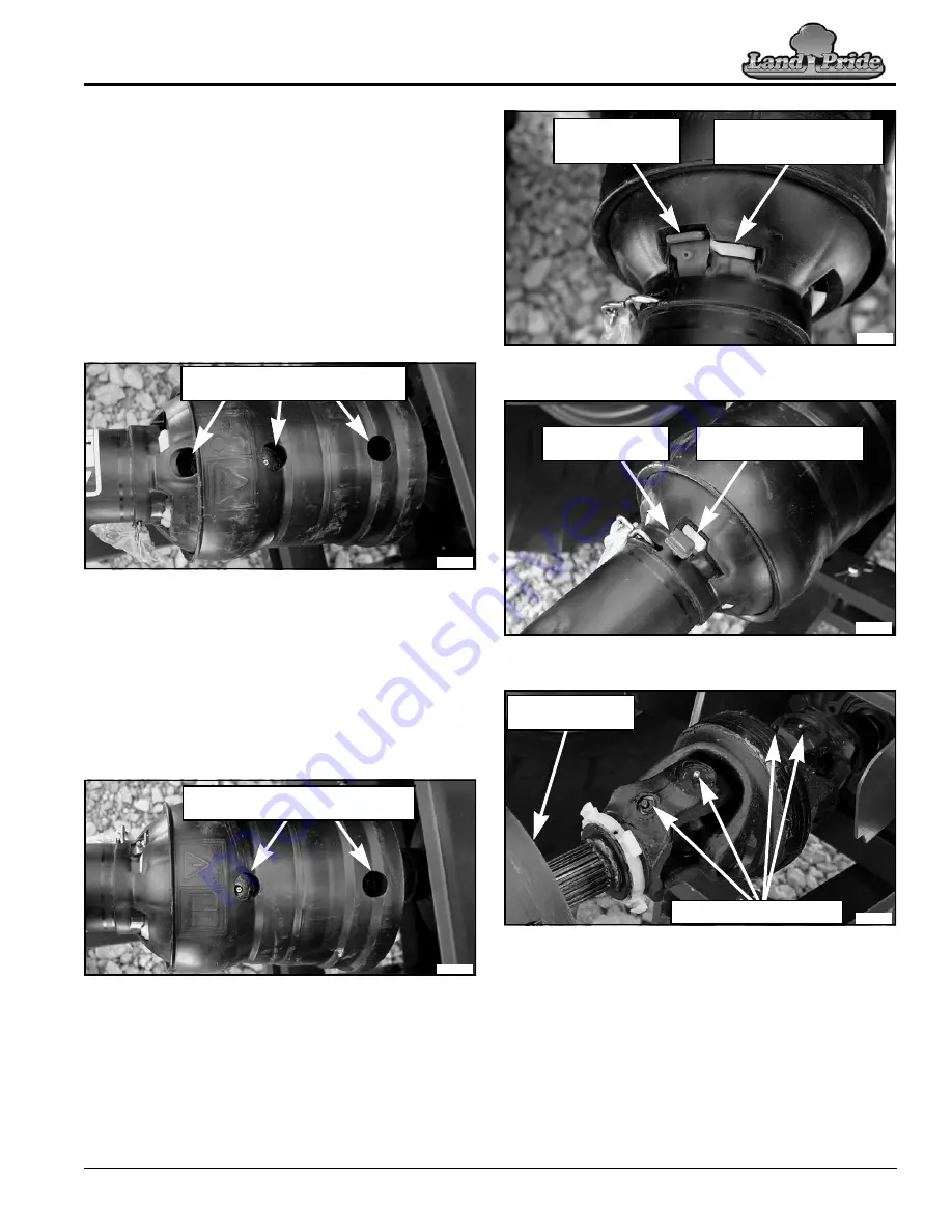
Lubrication Through Access Holes

1.

Refer to


Figure 5-14:


Rotate driveline shield until 

holes in shield align with grease zerks in CV joint. 

2.

Apply proper amount and type of lubrication. Refer to 

“CV Main Driveline Joints” 

on page 54 for 

quantities and type of lubrication.

Lubrication Through Three Holes In Driveline Shield

Figure 5-14

3.

Refer to


Figure 5-15:


Rotate driveline shield 180

o


until holes on opposite side of shield aligns with 
remaining grease zerks in CV joint.

4.

Repeat step 2 above on any grease zerks that were 
not greased in step 2. 

5.

Steps 1 tcan be repeated to lubricate universal 
joint on opposite end of driveline. (Opposite end of 
driveline has only one grease zerk.)

Lubrication Through Two  Holes  In  Driveline  Shield

Figure 5-15

Lubrication By Sliding Driveline Shields Back

1.

Refer to


Figure 5-16:


With a flat bladed screwdriver 

or similar tool, pry top of red locking tab up.

2.

Refer to


Figure 5-17:


Rotate white locking ring fully 

counterclockwise to the position shown.

3.

Refer to


Figure 5-18:


Pull back on driveline shielding 

until CV joint is exposed.

Rotate Driveline Shield to Align 

3-Holes in Shield With Grease Zerks

33992

33993

Rotate Driveline Shield to Align 

2-Holes in Shield With Grease Zerks

Locked Driveline Shield

Figure 5-16

Unlocked Driveline Shield

Figure 5-17

Slide Driveline Shield Back To Expose Grease Zerks

Figure 5-18

4.

Apply proper amount and type of lubrication. Refer to 

“CV Main Driveline Joints” 

on page 54 for 

quantities and type of lubrication.

5.

Slide driveline shield back to its operating position.

6.

Refer to


Figure 5-16:


Rotate white locking ring 

clockwise and press locking tab down until it snaps in 
place as shown.

7.

Steps 1 tcan be repeated to lubricate universal 
joint on opposite end of driveline.

Red Locking Tab 

Snapped Down 

Into Position

White Locking Ring 

Positioned On Right Side 

of Red Locking Tab

33994

Red Locking Tab 

Pried Up

White Locking Ring 

Rotated Counterclockwise

33995

Driveline Shield 

Pulled Back

Exposed CV Grease Zerks

33996

Summary of Contents for RC4615

Page 1: ...l Kit in French Language please see your Land Pride dealer Read the Operator s Manual entirely When you see this symbol the subsequent instructions and warnings are serious follow without exception Yo...

Page 2: ...ed the weights and measurements are no longer accurate for your machine Update the record by adding the machine weight and measurements provided in the Specifications Capacities Section of this manual...

Page 3: ...n Procedure 16 Standard Clevis Hitch Hook up 17 LP Performance Hitch Hook up 18 Bar Tite Hitch Hook up 19 Hydraulic Hook up 20 Right Left Wing Set up 20 Unfold Wings 21 Driveline Installation 21 Drive...

Page 4: ...e App on your smart phone open the App point your phone on the QR code and take a picture Dealer QR Locator The QR code on the left will link you to available dealers for Land Pride products Refer to...

Page 5: ...matter how much experience they may have should carefully read this manual and other related manuals before operating the power machine and this implement Thoroughly read and understand the Safety Lab...

Page 6: ...debris Always make sure any material and waste products from the repair and maintenance of the implement are properly collected and disposed Remove all tools and unused parts from equipment before ope...

Page 7: ...fore disconnecting hydraulic lines or performing work on the hydraulic system Make sure all hydraulic fluid connections are properly tightened torqued and all hydraulic hoses and lines are in good con...

Page 8: ...silica particles This dust can cause serious injury to the lungs silicosis There are guidelines which should be followed if crystalline silica quartz is present in the dust Be aware of and follow OSH...

Page 9: ...Important Safety Information 8 22 23 5 This page left blank intentionally...

Page 10: ...visit our dealer locator at www landpride com 3 Some new equipment installed during repair requires safety labels to be affixed to the replaced component as specified by Land Pride When ordering new...

Page 11: ...ion Table of Contents 8 22 23 RC4615 RCM4615 Rotary Cutters 331 644M 7 818 552C Danger Rotating Driveline Entanglement Hazard 37627 37586 37627 37586 818 142C Danger Rotating Driveline Located on all...

Page 12: ...15 RCM4615 Rotary Cutters 331 644M 8 818 276C Warning Rotating Blade Hazard 818 540C Danger Shield Missing DO NOT Operate Located on all driveline profiles 818 543C Danger Guard Missing DO NOT Operate...

Page 13: ...rmation Table of Contents 8 22 23 RC4615 RCM4615 Rotary Cutters 331 644M 9 37627 37586 37627 818 840C Danger Rollover Hazard 818 561C Warning Raised Wing Hazard Located on left right wings 818 714C Da...

Page 14: ...ieve pressure on system before repairing or adjusting or disconnecting Wear proper hand and eye protection when searching for leaks Use wood or cardboard instead of hands 838 094C WARNING 838 094C War...

Page 15: ...7 838 614C 2 x 9 Red Reflector Located on back side of left right wing lock bars 818 230C 1 11 16 x 2 13 16 Red Reflector Located on back side of right wing rear axle spindle 818 045C Warning Pinch Po...

Page 16: ...3 4 Amber Reflector Located on front side of left right wing lock bars 838 615C 2 x 9 Amber Reflector Located on front side of left wing only 838 615C 2 x 9 Amber Reflector Located on both sides of c...

Page 17: ...in diameter make them well suited for these applications All listed models offer a pull type narrow A frame hitch and Cat 6 constant velocity main driveline for attachment to 50 200 hp tractor The RC...

Page 18: ...necessary number of duplex outlets a control valve kit is available for adding an outlet See Hydraulic Accessories on page 41 for a complete description of this kit Before You Start Read and understa...

Page 19: ...ith customer supplied hitch pin to allow single person hook up Bar Tite Hitch Optional Refer to Figure 1 4 The bar tite hitch functions similar to LP Performance hitch except it clamps directly to the...

Page 20: ...page 28 3 Adjust park jack 9 until its base is firmly against the ground Spring Hose Loop Assembly Refer to Figure 1 7 1 Attach spring hose loop 10 to A frame hitch 2 with 3 8 16 x 1 GR5 bolt 11 flat...

Page 21: ...il holes in tractor drawbar and clevis hitch 9 are aligned 10 Shut tractor down properly before dismounting 11 Customer to supply hitch pin and hairpin cotter Insert hitch pin 1 through top hole in cl...

Page 22: ...s on page 14 NOTE Hitch pin 1 and hairpin cotter 2 are customer supplied 9 Raise or lower park jack 3 to align clevis 9 with tractor drawbar Drawbar should fit between lower and upper plates of clevis...

Page 23: ...ed to the cutter hitch make adjustments to the jack using Park Jack Angle Alignment instructions on page 28 3 Store center 3 point link in the tractor s storage hook 4 Start tractor raise 3 point arms...

Page 24: ...Shown Figure 1 15 Refer to Figure 1 15 1 Route hydraulic hoses 7 through hose support loop 10 and attach couplers to the tractor remote outlets If tractor has a float option on one of the outlets conn...

Page 25: ...wings with tractor hydraulic control lever until both wings are on the ground 1 4 3 27921 Transport Bar Storage Position Figure 1 15 Driveline Installation DANGER To avoid serious injury or death Do...

Page 26: ...ides of gearbox shield 10 and remove gearbox shield 7 Remove and discard rubber shaft protector 8 from splitter gearbox shaft 9 8 Remove locknuts 1 and bolts 2 from bolted coupler end of driveline 5 9...

Page 27: ...acers 4 is removed 2 Shut tractor down properly before dismounting Refer to Tractor Shutdown Procedure on page 16 3 Remove all stroke control spacers 4 from center hydraulic lift cylinder 1 by spreadi...

Page 28: ...steps 1 2 above once air is purged from the deck lift hydraulic system 6 Tighten hose fitting 5 at lift cylinder 4 Purge Wing cylinders Deck Lift Cylinder Figure 1 19 37910 Driveline Clearance Check C...

Page 29: ...ack stands under the four corners of the center deck 6 Return to the tractor seat and lower center deck onto the support blocks until cylinder hitch pin 2 is loose 7 Shut tractor down properly before...

Page 30: ...16 11 Replace stroke control spacers 2 as needed to support wheels at this position 12 With no one around or near the cutter move cylinder lift levers back and forth to release all hydraulic pressure...

Page 31: ...resting on its front skid shoes 25 Replace connecting pin bolt 1 as follows a For Standard Clevis Hitch See Figure 1 25 Insert hitch pin 1 into clevis hitch as shown Secure hitch pin with hairpin cott...

Page 32: ...ctions Front Skid Position Chain Guards Removed for Clarity Figure 2 2 Level Cutter Decks These adjustments should be made with cutter hooked to the tractor operating the unit or to a tractor having t...

Page 33: ...s to see if they are level with top of center deck If outer edge of either wing top is higher or lower than the center deck then that wing should be leveled as follows a If outer wing edge is higher t...

Page 34: ...hieved 8 Select required size and number of stroke control spacers 2 that will fit on the center hydraulic cylinder rod The following spacers are available Two 1 spacers One 1 1 4 spacer One 1 1 2 spa...

Page 35: ...Section 2 Adjustments Table of Contents 8 22 23 RC4615 RCM4615 Rotary Cutters 331 644M 31 This page left blank intentionally...

Page 36: ...make adjustments to the cutter with power take off engaged Cutter blades rotating at high speeds cannot be seen and are located close to the deck sides Body extremities will be cut off instantly Rota...

Page 37: ...sure that the rear tractor tires and lower 3 point arms do not make contact with cutter hitch driveline or deck Keep lower 3 point arms raised at all times when hitched to a pull type cutter Do not op...

Page 38: ...Blade Operation Inspection DANGER To avoid serious injury or death Tractor power take off shaft shield driveline shields and gearbox shaft shields must be installed and in good working condition to a...

Page 39: ...from tractor 4 See Figure 3 2 Remove hairpin clip 1 from storage lug 2 5 See Figure 3 3 Rotate end of transport lock bar 3 to cylinder pin 4 Secure with hairpin clip 1 6 Repeat steps 4 and 5 for the...

Page 40: ...locks before traveling on public roadways 4 When traveling on roadways transport in such a way that faster moving vehicles may pass you safely 5 Shift tractor to a lower gear when traveling over rough...

Page 41: ...oth cut without lugging tractor down See Select Gear Range above for detailed instructions 2 With wings lowered increase throttle to a speed just enough to get cutter started without stalling tractor...

Page 42: ...and appropriate reflective devices to provide adequate warning to pedestrians and other vehicle operators when traveling on public roads and in the dark of night Comply with all local state and feder...

Page 43: ...Section 3 Operating Instructions Table of Contents 8 22 23 RC4615 RCM4615 Rotary Cutters 331 644M 39 This page left blank intentionally...

Page 44: ...s 330 481A Front Single Row Chain Guards 330 493A Rear Single Row Chain Guards Double Chain Guards 330 483A Front Dual Chain Guards 330 495A Rear Dual Chain Guards Tire and Axle Options Land Pride off...

Page 45: ...l control kit is available from your local Land Pride dealer See Selector Control Valve Kit on this page Hydraulic Wing Control Kit Figure 4 2 27602 Selector Control Valve Kit Figure 4 3 Selector Cont...

Page 46: ...h the wing and divider gearboxes Repair driveline before putting cutter back into service 1 Pull cable hook with cable out past the gearbox 2 Attach cable to wing deck by routing cable around the wing...

Page 47: ...removed Air Filled Airplane Tires with split Rims Figure 5 1 33925 1 Section 5 Maintenance Lubrication General Maintenance Information Proper servicing and adjustments are key to the long life of any...

Page 48: ...k in the up position with solid supports before servicing underside of cutter IMPORTANT Cutting blades must be replaced in mating pairs Not replacing both blades will result in an out of balance condi...

Page 49: ...hat has been in use or has slipped for as little as only two or three seconds during run in may be too hot to touch Allow a hot clutch to cool before working on it Friction clutches must be capable of...

Page 50: ...periodically each week An additional set of scribe marks can be added to check for slippage See Figure 5 7 on page 46 to adjust spring length Clutch Disassembly Inspection Assembly Refer to Figure 5...

Page 51: ...periodically each week An additional set of scribe marks can be added to check for slippage 26618 Clutch Disassembly Inspection Assembly Refer to Figure 5 9 The clutch must be disassembled into its se...

Page 52: ...and left hand skid shoe 1 as shown 2 Plow bolts 2 should be checked for wear and replaced if necessary 3 Attach new left hand skid shoe 1 to cutter with existing 3 8 plow bolts 3 and secure with 3 8 h...

Page 53: ...ance on page 44 3 Inspect for loose damaged or worn parts and adjust or replace as needed 4 Repaint parts where paint is worn or scratched to prevent rust Ask your Land Pride dealer for aerosol touch...

Page 54: ...Purpose Grease Grease wheel bearings every 50 hours Quantity 2 pumps Repack wheel bearings annually 50 hrs Multi purpose spray lube Multi purpose grease lube Multi purpose oil lube Intervals in hours...

Page 55: ...eck Axle Pivot 3 zerks Type of Lubrication Multi purpose Grease 39201 39201 39201 Wing Deck Axle Pivot 4 zerks 2 zerks per wing axle Type of Lubrication Multi purpose Grease 50 Hours 50 Hours Adjustab...

Page 56: ...zerks Type of Lubrication Multi purpose Grease Quantity As required 50 Hours Bar Tite Hitch Optional 3 zerks Type of Lubrication Multi purpose Grease Quantity As required 50 Hours As Needed Park Jack...

Page 57: ...dipstick Allow time for air to bleed up from the lower cavity and then recheck 30215 Do Not Overfill NOTE Use a suction or siphon pump to drain gearbox of oil when there is not an oil drain plug 8 Hou...

Page 58: ...tion Multi purpose Grease Quantity 8 10 pumps IMPORTANT To extend the life of the constant velocity joint extensive lubrication must be performed every 8 hours of operation CV Main Driveline Joints CV...

Page 59: ...h Two Holes In Driveline Shield Figure 5 15 Lubrication By Sliding Driveline Shields Back 1 Refer to Figure 5 16 With a flat bladed screwdriver or similar tool pry top of red locking tab up 2 Refer to...

Page 60: ...rofile Tubes Type of Lubrication Multi purpose Grease Quantity Coat Generously Wing Driveline Joints Type of Lubrication Multi purpose Grease Drivelines with external profile tube grease point 37514 3...

Page 61: ...oses fittings stroke control spacers Wing hydraulics 3 x 12 hydraulic cylinders hoses fittings Wing transport protection Wing transport Locks Deck material thickness 10 gauge Side skirt thickness 1 4...

Page 62: ...4M 58 Transport Width Without Special Adjustments Transport Width With Wing Axles Disconnected At Turnbuckles 5 And Wheels Folded Back See Figure 1 13 on page 20 15 11 3 4 7 11 3 4 33486 33487 10 2 3...

Page 63: ...cutting of material 6 Blade overlap Eliminates skipping during turns Left wing rotates clockwise Better discharge of material Picks up tractor tracks 3 16 Round stump jumper Standard thick stump jump...

Page 64: ...cutting blades before lowering wings Tractor has instant on power take off Engage power take off at low rpm and then slowly increase engine speed to full power take off speed See Engage Blades on pag...

Page 65: ...230 405 300 3 4 10 235 170 360 265 510 375 M18 X 1 5 220 165 350 260 485 355 3 4 16 260 190 405 295 570 420 M20 X 2 5 280 205 440 325 610 450 7 8 9 225 165 585 430 820 605 M20 X 1 5 310 230 650 480 9...

Page 66: ...s not designed Misuse also specifically includes failure to properly maintain oil levels grease points and driveline shafts Claims under this Warranty should be made to the dealer which originally sol...

Page 67: ......

Page 68: ...Corporate Office P O Box 5060 Salina Kansas 67402 5060 USA...

Reviews: