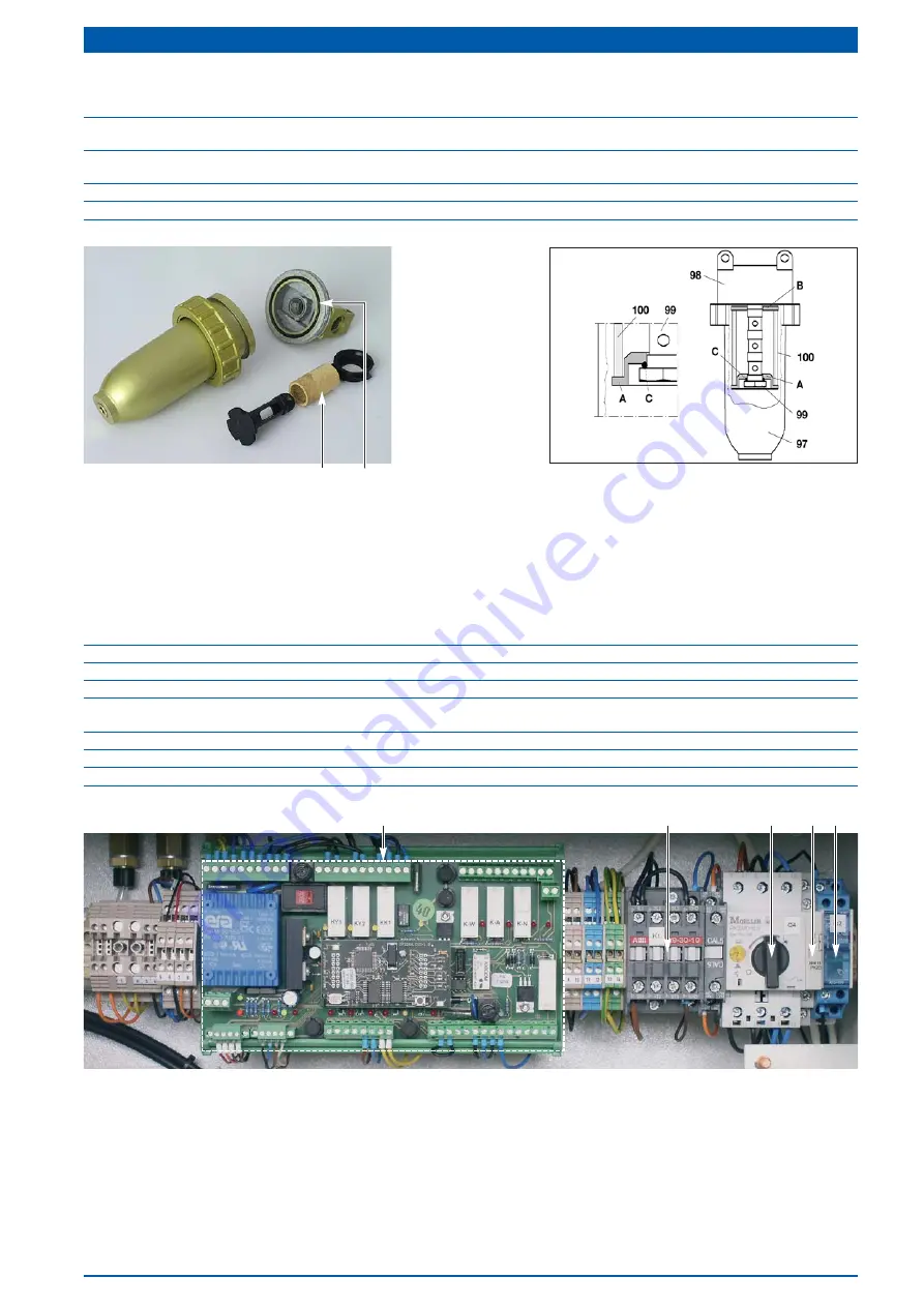
LANCIER Monitoring RTS 1000D Operating Instructions Manual Download Page 55

Page 55

Micro filter

Item Name

Order no.

Micro filter compl. (

33

RTS 1000D u. RTS 2600D

056358.000

Micro filter compl. (

33

RTS 5200D

057411.000

1*

Micro filter element (

96

RTS 1000D u. RTS 2600D

056359.000

Micro filter element (

96

RTS 5200D

057412.000

2

Seal (

97

)  (

B

)

056360.000

C

O-Ring (

RTS 5200D 

only) (

C

)

034390.000

1

2

Electrics

Item Name

Order no.

1

Auxiliary switch (

42

) of motor protective switch [Q4] (

5

)

067955.000

2

Motor contacter / switch [K1] (

56

)

073610.000

Auxiliary switch (

42

) of motor contacter / switch

073611.000

3

Motor protective switch [Q4] (

5

)  

RTS 2600D

067950.000

Motor protective switch [Q4] (

5

)  

RTS 1000D u. RTS 5200D

067951.000

4

Main switch signal voltage DC [Q2] (

6

)

073370.000

5

Multifunktional relay MFR (

73

)

073285.000

6

Power pack 230 V AC/60 DC (Option, no illustration)

071662.000

5

2

3

1

4

Summary of Contents for RTS 1000D

Page 1: ...Operating instructions RTS 1000D RTS 2600D RTS 5200D Pressurisation systems with Minidisplay BA 073707 020 01 13...

Page 2: ...ation 15 Pressurised air supply storage drying and monitoring 16 Multifunctional Relay MFR 18 Electrics 19 Mounting 20 Wall mounting RTS 1000D 20 Setting up the system RTS 2600D and RTS 5200D 20 Setti...

Page 3: ...00D 44 2 Servicing air dryer 46 3 Servicing double non return valve 47 4 Servicing pressure limiting valve and micro filter 47 5 Servicing micro filter 47 6 Cyclone water separator RTS 5200D only 48 7...

Page 4: ...300 l h 10 ca 750 l h 10 ca 1500 l h 10 Regeneration time drying agent container 60 s 60 s 60 s Content air storage tank 6 l 40 l 60 l Content reserve air storage tank Option 250 l 250 l Ambient tempe...

Page 5: ...h the enclosed CE Declaration of Conformity see the back of this operating instruction Symbols used Attention Danger This symbol warns of the health risks up to threatening injuries or death Warning D...

Page 6: ...you to carry out maintenance and repair work on the pressurization sys tem yourself for daily use It contains safety instructions which must be observed During operation other instructions must be ob...

Page 7: ...tant It is imperative to read and observe the safety instructions prior to start up The operating instruction must always be stored within reach For the safety of persons in charge Operator Operator i...

Page 8: ...ific faults which may compromise safety have to be corrected immediately The pressurization system RTS 1000D RTS 2600D and RTS 5200D must only be installed operated serv iced and repaired by persons w...

Page 9: ...al equipment must be protected against direct contact according to their volt age frequency usage category and place of operation by insulation position arrangement or permanent fit tings The electric...

Page 10: ...equipment has to be started up a second per son should always be present to disconnect the equipment in an emergency situation Always carry out work with greatest care and attention Watch out for the...

Page 11: ...in the condensate surge tank The air dried in this way is stored in the air storage tank with a pressure between 3 0 and 5 5 bar A pressure monitor ensures sufficient compressed air in the air storag...

Page 12: ...4 Equipment output 5 Motor protective switch Q4 to manually switch the compressor on and off features a built in protective relay to protect the motor from excessive current consumption 6 Main switch...

Page 13: ...onnection of a second pressurisation system e g for maintenance and repair services 76 Condensate surge tank 90 Door switch S8 Option interrupts the signal output when actuated reactivates the signal...

Page 14: ...1 displays the pressure in the air storage tank 9 1 14 Minidisplay shows the most important system parameters and allows for their manipulation 15 Total air flow meter 15 2 displays the total air flo...

Page 15: ...ignal LED A illuminates when the common system signal is pending runtime fault T humidity fault F high pres sure fault H or compressor fault M 42 Signal LED W illuminates when the preset maintenance i...

Page 16: ...sure 14 1 restricts the air flow to the outlet so as to prevent exceeding the maximum quantity delivered to the equip ment 28 Non return valve 4 1 prevents a reversed flow of pressurised air from the...

Page 17: ...ensor for MFR monitors the relative humidity of the output air When reaching the upper limit the MFR activates fault F and shuts the system down 115 Test flange 7 3 for air tank inspection RTS 2600D R...

Page 18: ...On 55 Signal LED T Runtime 56 Signal LED Ext Signal in 57 Signal LED Ext Signalization 59 Signal LED Y1 state 60 Signal LED Y2 state 61 Signal LED Comp OK 62 Signal LED State Comp in 63 Signal output...

Page 19: ...he motor contacter switch 72 K1 and activates the signal F when the humidity content of the dried air is inadmissibly high monitors the running time of the compressor max approx 90 min and prevents po...

Page 20: ...d strains LANCIER Monitoring assumes no liability whatsoever for wall mounting The place of mounting should be dry and swept clean Minimum distance to adjacent walls and equipment 400 mm Setting up an...

Page 21: ...with 1 phase PE protective earth to green yellow N neutral to blue L1 Phase to black or brown 5 core with 3 phases PE protective earth to green yellow N neutral to blue L1 Phase to black L2 Phase to...

Page 22: ...nate 49 51 47 64 66 Set the equipment into operation charge equipment Main switch signal voltage DC 6 is switched on Turn motor protective switch 5 to I The compressor starts Check indications of Mini...

Page 23: ...At least one of the red LEDs of the 8 digit humidity display 39 7 and 8 digit illuminate The red LED A 41 illuminates on the Minidisplay 13 The red Signal LED F 48 illuminates in the MFR pressurised...

Page 24: ...Close safety valve high pressure 25 Then carry out function testing Remount connecting block cover 11 MFR 52 48 54 67 49 51 59 61 62 47 63 65 The humidity monitoring activates itself automatically af...

Page 25: ...ponents Risk of injury Take caution with heated components Check and set reference value motor protective switch back up fuse Check setting Reference value of setting screw 78 RTS 1000D 230 V 50 Hz ca...

Page 26: ...25 7 31 30 B Pressure switch cable pressure too high 30 Close shut off valve 9 Increase cable pressure by turning the pressure reducer 7 to the right observe cable pressure manometer 12 the pressure...

Page 27: ...re 12 must display 12 the required cable pressure otherwise Set cable pressure to the value in keeping with the order Operating voltage is switched on shut off valve 9 is closed Turn the setting screw...

Page 28: ...pressure and then the cut in pressure because changing the cut out pressure leads to a change in the cut in pressure This means the difference between cut out and cut in pressure stays the same Once...

Page 29: ...limiting valve 34 and the manometer high pressure 13 so the manometer high pressure 13 can be used as a test gauge Close safety valve high pressure 25 Switch on operating voltage The manometer high p...

Page 30: ...t LED A 64 illuminates on the MFR If the humidity shut down process is not executed discharge tank again by opening safety valve high pressure 25 in order to start a new compressor run Close safety va...

Page 31: ...on of the pressurisation system In order to get immediate humidity moni toring the F off operation must be overridden Press button F Off 44 of the Minidisplay or 67 of the MFR for approx 5 seconds The...

Page 32: ...red by the manufacturer only Check the watchdog timing compressor Deadly risk Working on open live equipment Do not operate the equipment with damp hands Caution live components Setpoint value The max...

Page 33: ...if a signal line is connected 45 41 42 Check door switch Option RTS 2600D RTS 5200D only Deadly risk Working on open live equipment Do not operate the equipment with damp hands Caution live component...

Page 34: ...urised air consumers Assignment outputs flow meters RTS 2600D und RTS 5200D If flow meters are installed the assignment to the connect ion nozzle is as follows Flow meters read line by line from left...

Page 35: ...ry system Set mobile system into operation while observing the respective instruction manual and safety instruc tions Retrofit kit signalisation for emergency mode For easy and quick connection of the...

Page 36: ...lization 68 was activated 66 Signal LED Option ext Tank illuminates when signal A was activated an pressurised air is supplied from an optionally connected backup air storage tank 89 Signal LED Signal...

Page 37: ...motor protec tive switch Q4 5 When the the stationary system is switched on again the monitoring of the mobile emergency system is shut down automatically Signal LED Ext Signalization 57 turns off The...

Page 38: ...en cabinet door Close shut off valve 9 2 Interrupt signal output RTS 2600D and RTS 5200D equipped with optional door switch 90 only to avoid the forwarding of fault signalisation effected by servicing...

Page 39: ...display 14 for 5 seconds The value is reset to 400 The Signal output LED W 63 of the MFR 73 turns off The remaining operating hours until the next maintenance are indicated in the Minidisplay 14 89 69...

Page 40: ...tightening the connecting nut on the filter head 94 RTS 5200D Clean seals A B and C if necessary replace worn seals Cover hollow grub screw 95 with O ring C and then with seal A Screw hollow grub scre...

Page 41: ...off valve 9 Close cabinet door The optional signal interruption by the door switch 90 will be retracted LED signal interruption 89 turns off in the MFR 73 5 Measure humidity of air e g with psychrome...

Page 42: ...ead 20 Undo cylinder head screws 18 Remove cylinder head 20 suction and pressure valves with seals 21 25 Undo fastening screws 18B of cylinder 26 and remove cylinder from pistons 1 3 Clean and if nece...

Page 43: ...Page 43 Compressor VD 7 2 RTS 1000D and VD 28 2 RTS 2600D B...

Page 44: ...ssor parts Dry clean all parts Replace damaged or worn valves Replace seals for cylinder and cylinder head 1 4 Assemble compressor Fit both piston rings 27 turned 180 Replace backer strip 29 and sprin...

Page 45: ...Page 45 Compressor VD 50 4 RTS 5200D...

Page 46: ...rying agent container Dry clean all parts Replace worn o rings M Replace filter discs L and O Replace worn sealing rings L and N 2 4 Assemble drying agent container Insert new filter disc O PE sealing...

Page 47: ...34 Pull back plastic cap 106 for release and turn anti clock wise as far as it will go to relieve the valve Unscrew upper housing 107 from base part 108 Take out setting screw 109 spring 110 and press...

Page 48: ...of the whole system for impermeability 10 After maintenance If necessary re establish connection to consumer load and open shut off valve 9 Close door Causes and remedy of faults Signal Fault Cause Re...

Page 49: ...maintenance of double non return valve see page 47 replace if nec essary Check cycle time see page 32 Watch relay KY1 u KY2 check wiring and plugs of solenoid valves Check solenoid valves and replace...

Page 50: ...fuses Depressurise equipment Open safety valve high pressure 9 for this Close safety valve high pressure 9 2 Search for and remedy faults according to charts Causes and remedying of faults pages 48 a...

Page 51: ...idity monitoring RTS 2600D 5200D Warning Pressing the button F off overrides the humidity monitoring The button must be used only if a fault occurred the high pressure safety valve 25 is open and the...

Page 52: ...compl 073282 000 9 Pressure switch high pressure 2 0 bar RTS 2600D RTS 5200D only no illustration 045416 000 10 Pressure monitor 36 006464 000 11 Non return valve 28 053093 000 12 Safety valve cable...

Page 53: ...r 25 023791 000 9 Non return solenoid valve block 114 no illustration position only 021551 000 10 Membrane pressure limiting valve 113 no illustration 030077 030 11 Micro filter compl 33 see page 54 1...

Page 54: ...lar sieve 1 00 kg RTS 1000D u RTS 2600D 064786 000 Molecular sieve 2 25 kg RTS 5200D 022528 000 2 Cylinder tube RTS 1000D u RTS 2600D 004482 000 Cylinder tube RTS 5200D 019453 000 3 Mounting bolt RTS...

Page 55: ...y C 034390 000 1 2 Electrics Item Name Order no 1 Auxiliary switch 42 of motor protective switch Q4 5 067955 000 2 Motor contacter switch K1 56 073610 000 Auxiliary switch 42 of motor contacter switch...

Page 56: ...F 533 019763 000 39 Cap AF 535 019765 000 40 Olive AF 567 A 019767 000 Service packet K 260 019771 000 Compressor RTS 2600D type VD 28 2 Item Name Order no Compressor type VD 28 2 compl 34 011595 000...

Page 57: ...Compressor VD 7 2 and VD 28 2 Page 57...

Page 58: ...ve plate AF 543 019739 000 23 Suction valve AF 544 019741 000 24 Cylinder seal AF 521 019743 000 25 Cylinder AF 509 019745 000 26 Piston ring AF 541 011601 000 27 Backer strip AF 540 019749 000 28 Pis...

Page 59: ...Page 59 Compressor VD 50 4...

Page 60: ...valve Interim pressure 11 1 Manometer High pressure 11 2 Manometer Cable pressure 1 11 3 Manometer Cable pressure 2 11 4 Manometer Interim pressure 11 5 Contact manometer High pressure 11 6 Contact m...

Page 61: ...Page 61 Pneumatics diagram RTS 1000D RTS 2600D and RTS 5200D no 073445 072...

Page 62: ...gnal relay H K15 Signal relay N K16 Time relay 8 min 1 K17 Time relay 8 min 2 K18 Switch clock K19 Switching relay K20 Signal relay W K21 Time relay Backlash K22 Switching relay K23 Signal relay V M1...

Page 63: ...Page 63 Circuit and wiring diagram RTS 1000D RTS 2600D und RTS 5200D no 073659 000...

Page 64: ...gnal relay H K15 Signal relay N K16 Time relay 8 min 1 K17 Time relay 8 min 2 K18 Switch clock K19 Switching relay K20 Signal relay W K21 Time relay Backlash K22 Switching relay K23 Signal relay V M1...

Page 65: ...Page 65 Circuit and wiring diagram RTS 1000D RTS 2600D und RTS 5200D no 073586 000...

Page 66: ...Page 66...

Page 67: ...Page 67...

Page 68: ...nsulted EN 12100 1 und 2 Machine safety EN 286 1 Simple imitation pressure tank for air or nitrogen part 1 EN 60204 1 Electrical fittings of machines EN 61000 6 1 and 2 Interference resistance fault f...

Reviews: