background image

24

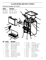
Item  Part No. 

Description

  1 

05-3242/01 

Nozzle, Black

  2 

82-5139 

Flavor Shot Assembly, FSM, Refresh

  3 

52-3822 

Flavor Shot Keypad Panel Assembly

  4 

05-3287 

Bonus Flavor Injector

  5 

05-3540-01 

Refresh Merchandiser, FSM, 30”, 


10 Valve

  - 

05-3542-01 

Refresh Merchandiser, FSM, 30”, 


8 Valve

  -  

05-3548-01  

Refresh Merchandiser, FSM, 25”, 


8 Valve

  6 

52-3701 

ADA Button Panel Assembly

  7 

04-0774 

Thumb Screw

  8 

30-12838 

Flavor Shot Bracket

3

10

11

12

13

8

14

9

17

18

6

2

1

16

15

4

5

7

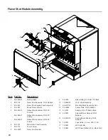
Flavor Shot Module Assembly

  9 

05-1385 

Elbow Fitting, 0.5 Dole x 0.2 Barb

  10  19-0262/03 

LFCV Valve Assembly

  11  82-2317/01 

Mounting Block Assembly, SGL

  12  30-12885 

Faucet Plate, FSM, Refresh

  13  01-2724 

Adaptor, SS .175 Barb x Dole

  14  52-3830 

Solenoid/Valve Harness, FSM, 


Refresh

  15  52-3816/01 

Control Board Housing, FSM, 


Refresh

  16  12-0550 

Fuse Holder, In-Line, 500 V, 15 A

  17  12-0643 

LED Light Bar

  18  12-0652 

LED Driver, Ballast, 60 W, Mean Well

Summary of Contents for Blue Star CB Series

Page 1: ...l rights reserved 4500 Lancer Corporation 6655 Lancer Blvd San Antonio Texas 78219 800 729 1500 Tech Support Warranty 800 729 1550 email custserv lancercorp com web lancercorp com Lancer PN 28 0946 03...

Page 2: ...Bin Ice Chute Carbonator Pump Troubleshooting 21 Remote Syrup Flavor Shot Pump Troubleshooting 22 ILLUSTRATIONS AND PART LISTINGS 23 27 Main Unit Assembly 22 25 30 23 Flavor Shot Module Assembly 24 P...

Page 3: ...d as a substitute for unplugging the dispenser from the power source to service the unit Only qualified personnel should service internal components of electrical control housing WARNING Make sure tha...

Page 4: ...SIONS Width 22 0 inches 559 mm Depth 30 5 inches 775 mm Height 40 25 inches 1022 mm WEIGHT Shipping 310 lbs 141 kg Empty without Ice 280 lbs 127 kg Ice Capacity 200 lbs 91 kg ELECTRICAL 115 VAC 60 Hz...

Page 5: ...3 6 Amps PLAIN WATER SUPPLY Min Flowing Pressure 75 PSIG 0 516 MPA CARBONATED WATER SUPPLY Min Flowing Pressure 25 PSI 0 172 MPA Max Static Pressure 65 PSI 0 448 MPA CARBON DIOXIDE CO2 SUPPLY Min Pres...

Page 6: ...PSIG 0 516 MPA CARBONATED WATER SUPPLY Min Flowing Pressure 25 PSI 0 172 MPA Max Static Pressure 65 PSI 0 448 MPA CARBON DIOXIDE CO2 SUPPLY Min Pressure 70 PSIG 0 483 MPA Max Pressure 80 PSIG 0 552 M...

Page 7: ...Closed B Carb Water ON E Syrup Closed C Syrup ON D There is 100 flexibility on the 22 6 valve and the 30 8 valve dispensers The 30 10 valve and the 25 8 valve dispensers have space restrictions so th...

Page 8: ...ubing Oetiker Clamp Fittings Water Booster Lancer PN 82 3401 or MC 163172 Water Regulator supplied with unit CONSIDER THE FOLLOWING BEFORE INSTALLATION Location of Water Supply Lines Location of Drain...

Page 9: ...flake ice in the dispenser NOTE The dispenser should only be installed in a location where it can be overseen by trained personnel NOTE 4 Unit may be installed directly on countertop or on legs If ins...

Page 10: ...spensing mechanism The bracket for mounting a thermostat is located in the ice bin During the automatic agitation cycle and while dispensing ice ensure there is ade quate space between the top of the...

Page 11: ...to drain may cause the Drain Tube to become clogged with coffee or tea grounds or other solid particles ATTENTION Remote Pump Installation 1 If necessary install water booster Lancer PN MC 163172 betw...

Page 12: ...the tee fitting at syrup pumps A B C A Syrup Pump Outlet B Syrup Pump C Fitting 4 Connect tubing from dispenser syrup inlet to the syrup pump outlet fitting Repeat for each syrup line pump and flavor...

Page 13: ...ubing routed from the tee at the syrup pumps to the second outlet of the low pressure CO2 regulator manifold 7 Repeat Step 6 for both low pressure CO2 regulators on the regulator manifold routed to th...

Page 14: ...mately 1 2 of the bin before plugging in the unit 5 Connect unit power cord to grounded electical outlet A Pressure Relief Valve B CO2 Inlet C Valve Lever A B C 9 Turn on CO2 at the source then using...

Page 15: ...g counter clockwise and pulling down then remove diffuser by pulling down 5 Install Lancer yellow syrup seperator PN 54 0031 in place of nozzle 6 Re open syrup shut off at mounting block 7 Activate va...

Page 16: ...ng solution is removed from the system ATTENTION Cleaning and Sanitizing Solutions Cleaning Solution Mix a mild non abrasive detergent e g Sodium Laureth Sulfate dish soap with clean potable water at...

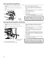
Page 17: ...Activate each valve until lines are filled with cleaning solution then let stand for ten 10 minutes 7 Flush out cleaning solution from the syrup lines using clean warm water 1 Disconnect the four 4 fl...

Page 18: ...sanitizing solution and let sit for fifteen 15 minutes 6 Set nozzle and diffuser aside and let air dry DO NOT rinse with water after sanitizing 7 Reconnect diffuser and nozzle 8 Connect power 9 Taste...

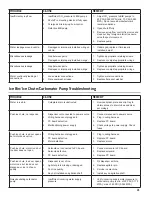
Page 19: ...ated 1 Keyswitch is off or keyswitch harness is disconnected 2 No power to dispenser 3 Malfunctioning switch assembly 4 Malfunctioning power supply 5 Malfunctioning PCB board 6 Malfunctioning VersaPou...

Page 20: ...ply Adjust CO2 pressure to 70 PSI 0 483 MPA 2 Need water booster kit 3 Replace carbonator pump 4 Replace backflow preventer noting the flow direction arrow from pump to coldplate 5 Replace probe 6 Rep...

Page 21: ...obstructed 1 Remove splash plate and drip tray to obtain access to drain tubes and clear accordingly Push ice chute no response 1 Dispenser not connected to power source 2 Wiring harness not plugged...

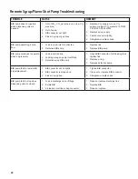
Page 22: ...continues to operate when bag is empty 1 Leak in suction line 2 Leaking o ring on pump inlet fitting 3 Defective syrup BIB pump 1 Check BIB connector if still leaking then replace line 2 Replace o rin...

Page 23: ...Merchandiser Sub Assy IBD22 05 3357 01 Merchandiser Sub Assy IBD30 7 64 5031 01 01 PCB Assy Backlight Part No Description 85 4528CB 211P IBD25 4500 115 60 8V 85 4546CB 211P IBD22 4500 115 60 6V 85 454...

Page 24: ...nel Assembly 7 04 0774 Thumb Screw 8 30 12838 Flavor Shot Bracket 3 10 11 12 13 8 14 9 17 18 6 2 1 16 15 4 5 7 Flavor Shot Module Assembly 9 05 1385 Elbow Fitting 0 5 Dole x 0 2 Barb 10 19 0262 03 LFC...

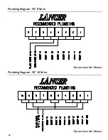
Page 25: ...25 Plumbing Diagram 22 Plumbing Diagram 25 Syrup Lines Not Shown Syrup Lines Not Shown...

Page 26: ...26 Plumbing Diagram 30 8 Valve Plumbing Diagram 30 10 Valve Syrup Lines Not Shown Syrup Lines Not Shown...

Page 27: ...to the environment from improper disposal recycle the unit by locating an authorized recycler or contact the retailer where the product was purchased Comply with local regulations regarding disposal o...

Page 28: ...Lancer Corp 800 729 1500 Technical Support Warranty 800 729 1550 custserv lancercorp com lancercorp com...

Reviews: