


8
Following sanitization, rinse with end-use product
until there is no aftertaste. Do not use a fresh water
rinse. This is a NSF requirement. Residual sanitizing
solution left in the system creates a health hazard.
!
CAUTION
11.
Disconnect CO
2
line and syrup line from tank filled with
cleaning solution then reattach lines to tank filled with water
and pressurize.
12.
Activate valve to flush cleaning solution from the line.
13.
Disconnect CO
2
line and syrup line from tank filled with water
then fill a seperate tank with sanitizing solution.
14. Connect both CO
2
and syrup lines to tank filled with
sanitizing solution and pressurize.
15.
Activate valve to fill line with sanitizing solution then let stand
for ten (10) minutes.
16. Disconnect lines from the sanitizer tank and reattach to
syrup tank and pressurize.
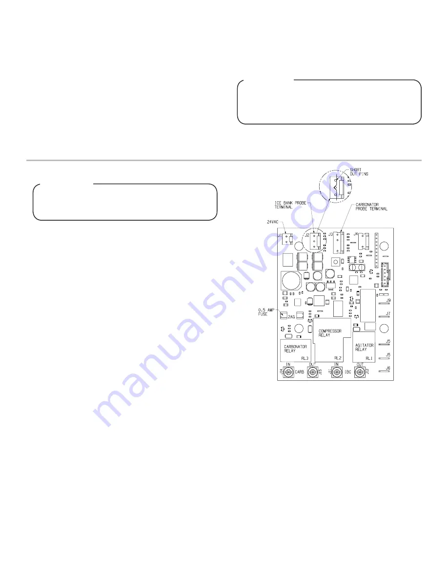
THE ELECTRONIC ICE BANK CONTROL (EIBC)
Checking for Normal PCB Operation
9.
Turn electrical power OFF for 15 seconds and then back ON again to reset Carbonator timer. Again, measure continuity of the PCB
screw lug connections
•
Terminal 3 to 4 (Carbonator): During the first 2.5 to 3.5 minutes there should be continuity. After 2.5 to 3.5 minutes, there
should be NO continuity.
•
Terminal 2 to 1 (Compressor): During first 4 to 6 minutes, there should be NO continuity. After 4 to 6 minutes, there should be
continuity. There should be NO continuity from 2 to 1.
•
You should be able to hear a “click” sound of the relay closing when the time delay ends.
10.
If all the above work as noted, then the board is functioning properly. Remove tape and reconnect board. If any non-conformities
are found, the PCB must be replaced (PN 52-1423/01).
•
Terminal 3 to 4: There should be continuity. Use a short copper wire, paper clip, or other means to short the Carbonator probe
terminals (J3) on the PCB by touching all three (3) pins together. This should be done before the 2.5 to 3.5 minute time limit
has elapsed. Measure the continuity again between Terminal 3 to 4: There should be
NO
continuity.
Terminal block has AC line voltage and should be
covered with tape. Tape should cover bare electrical
connections to prevent electrical shock.
!
WARNING
1. Turn power OFF or insure that power has been disconnected
from dispenser
2. Check condition of 0.5 amp fuse at location shown in
diagram to the right. If fuse is blown, trace cause of short in
valve wire harness and associated 24 VAC lines and replace
fuse. If fuse is good, continue with next step.
3.
Disconnect leads from the terminal block that connect to the
PCB, noting their specific location for reconnection.
4.
Disconnect both the Ice Bank probe (J2) and the carbonator
probe (J3) (if equipped) connections from board.
5. Use a short copper wire, paper clip, or other means to short
the Ice Bank probe terminals (J2) on the PCB by touching all
three (3) pins together.
6.
Set Ohm test meter to measure continuity.
7.
Reconnect power or turn dispenser ON.
8. Observe time and check continuity of the PCB screw lug
connections:
17. Draw drinks and refill line with end use product to flush
sanitizing solution from the line.
18.
Taste the drink to verify that there is no off-taste. If off-taste
is found, flush syrup system again.
19.
Repeat procedure for each valve/syrup tank.
Summary of Contents for 2500 REMOTE series
Page 11: ...11...


