


6
Pump Motor will run for a few seconds to fill carbonator
tank
NOTE
6.
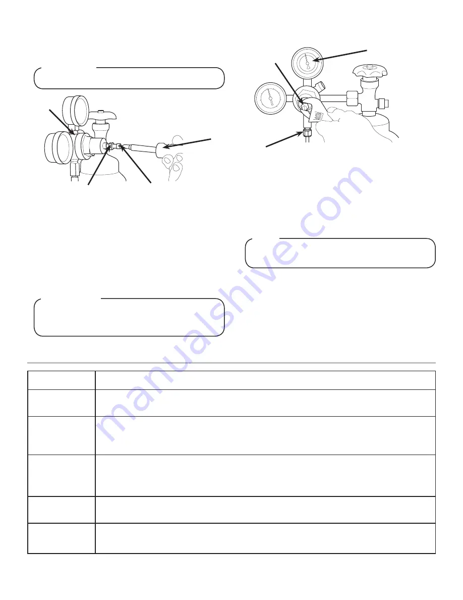
Using a wrench, loosen lock nut on the regulator adjustment
screw of the high pressure CO
2
regulator connected to the
source, then using a screwdriver back out lock nut screw all
the way.
7. Repeat Step 6 for both low pressure CO2 regulators on the
regulator manifold routed to the unit and the syrup pumps.
8.
Purge the water to fill carbonator tank by opening carbonator
relief valve. Close relief valve once water begins to comes
out of relief valve.
9. Activate each valve on the dispenser until a steady flow of
water is achieved.
10.
Unplug the unit then unplug the Pump Motor Connector from
the control box. Use the wiring diagram on the unit control
box for reference.
11. Turn on CO
2
and using a screwdriver, adjust regulator to 75
PSI (0.517 MPA) then tighten lock nut with wrench.
12. Adjust both of the low pressure regulators on the regulator
manifold to 75 PSI (0.517 MPA) then tighten locknut with
wrench.
13.
Activate each valve until gas-out is achieved.
14.
Plug the Pump Motor Connector back into the control box
then plug in unit.
15.
Re-attach bonnet and front plate.
16. Activate each valve until a steady flow of carbonated water is
achieved.
DO NOT TURN ON CO
2
SUPPLY AT THIS TIME
!
WARNING
A. CO
2
Regulator
B. Screwdriver
C. Loosened Lock Nut
D. Regulator Adjustment Screw
A
B
C
D
Failure to disconnect the motor power supply will
damage the carbonator motor, the pump and void the
warranty
F
ATTENTION
A. Regulator Adjustment Screw
B. Adjust to 75 PSI (0.517 MPA)
C. Wrench
A
B
C
As Needed
•
Keep exterior surfaces of dispenser (include drip tray and cup rest) clean using a clean, damp cloth.
Daily
•
With a clean cloth and warm water, wipe off all of the unt’s exterior surfaces.
DO NOT USE ABRASIVE
SOAPS OR STRONG DETERGENTS.
Weekly
•
Taste each product for off tastes.
•
Remove the unit’s bonnet and check the level of water in the water bath. Replenish as required, and
replace the bonnet.
Monthly
•
Unplug the dispenser from the power source.
•
Remove the bonnet and clean the dirt from the condenser using a soft brush.
•
Replace the bonnet and plug in the unit.
Every Six Months
•
Clean and sanitize the unit using the appropriate procedures outlined in the Cleaning and Sanitizing
section of this guide.
Yearly
•
Clean water bath interior, including evaporator coils and refrigeration components.
•
Clean the entire exterior of the unit.
SCHEDULED MAINTENANCE
Summary of Contents for 2500 REMOTE series
Page 11: ...11...