LEGACY FG
033-0004
Page S.10
REV. 0/04-23-2007
Supplement–Legacy Fixed Gear
Lancair International Inc., Represented by Neico Aviation Inc., Copyright 2007 Redmond, OR 97756
S.4.C Setting the Toe-in
In this section you will be setting the main gear’s toe-in
angle to 0.5°. We want to emphasize that the precision of
this setting is extremely important for ground handling and
tire wear.
Steps...
1. Attach the axle mount to the gear leg by slightly
snugging the set screw.
2. Using the fuselage center line that you drew on the
location for the toe-in lines:
The toe-in lines must:
• Be parallel to the fuselage center line.
• Be directly below the alignment tool using a plumb
bob as shown.
• Extend 3’(1 meter) in front of the gear leg.
3. Attach a 3.5’ (1.25 meters) or longer alignment tool to
the end of the gear leg.
Notice that the forward hole on the end of the axle
mount has some slack and the set screw can be
loosened and tightened as needed for leveling the
alignment tool.
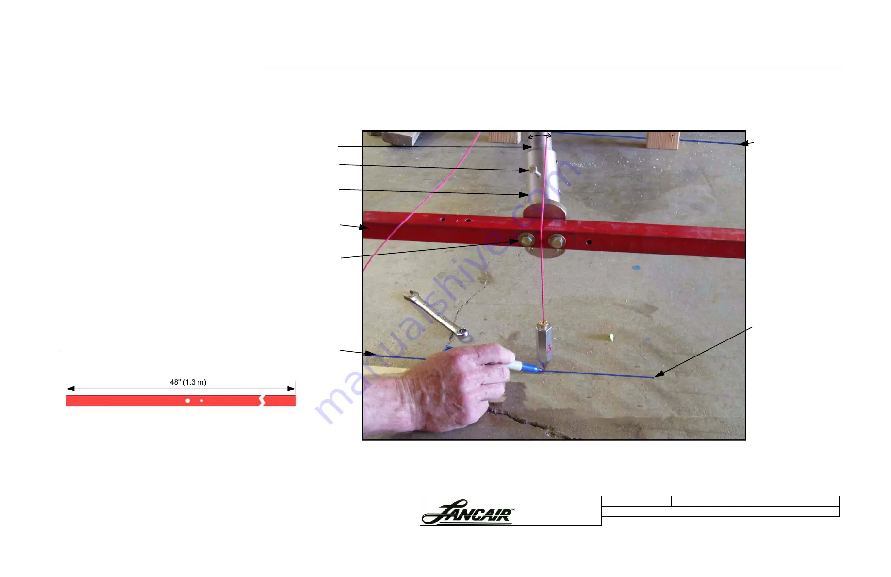
4. Hang a plumb-bob as shown in Figure S.4.C.2 and
mark its position on the floor.
5. Make a mark on the alignment tool, 3’ (1 meter)
forward of the center of the end of the gear leg.
6. Hang a plumb bob at this spot. See Figure S.4.C.4 on
the next page.
Note:
This process can also be done using a laser level.
Figure S.4.C.1 Alignment tool
Figure S.4.C.2 Marking the gear leg location in relation to the toe-in base line
Gear leg
7702
Set screw
Axle mount
7705-01
Alignment tool
Toe-in line
Leave some slack
in the forward hole.
Make sure the
alignment tool is level.
Rotate the gear leg until the
alignment tool is level.
This toe-in line is placed:
– Parallel to the fuselage
center line.
– Directly below the
alignment tool by using a
plumb bob as shown.
– Extends 3’ (1 meter) in
front of the gear leg.
Tip:
Once the alignment
tool is level, cut two
wooden blocks of equal
height. Place one directly
behind the plumb bob
hanging from the gear leg
and place the other 3’ in
front of the gear leg.
Center Line


