background image

Lanberg © 2015-2023

13

 PL

2. Montaż

Należy ściśle przestrzegać zaleceń zawartych w tej instrukcji.

2.1   Przygotowanie

Przygotuj odpowiednią ilość miejsca na podłożu na którym odbędzie się montaż. Ostrożnie wyjmij wszystkie elementy z kartonu 

transportowego. Dalsze instrukcje montażu będą opierać się o zawarty schemat. 

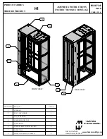
2.1.1. Zestawienie elementów

Części szafy

Nr. elementu

Nazwa

Rysunek elementu

Wymagana liczba

Liczba w zestawie

Element A

Drzwi przednie szklane 

1 szt.

1 szt.

Element B

Panel tylny 

1 szt.

1 szt.

Element C 

Panel boczny

2 szt.

2 szt.

Element D

Rama 

2 szt.

2 szt.

Element E

Pokrywa górna 

1 szt.

1 szt.

Element F

Dolna pokrywa

1 szt.

1 szt.

Element G

Listwa poprzeczna

15U~27U 4 szt.

32U~42U 6 szt.

Element H

Pokrywa wentylatora

1 szt.

1 szt.

Element I

Szyna montażowa

4 szt.

4 szt.

Element J

Zaślepka panelu

Płaska 3 szt.

Z wyżłobieniem 4 szt.

Element K

Nóżki szafy

4 szt.

4 szt.

i

Summary of Contents for FF01 12U

Page 1: ...a obs ugi 19 Rack cabinets with panel LCD FF01 12U 15U 22U 27U 32U 37U 42U 47U 600 600 600 800 600 1000 600 1200 Szafy stoj ce 19 z panelem LCD FF01 12U 15U 22U 27U 32U 37U 42U 47U 600 600 600 800 600...

Page 2: ...this product please contact the retail outlet where the product was purchased or request information from the local authority 1 3 General safety precautions The device specifications must be strictly...

Page 3: ...nto antistatic bags if possible when they are not in use 1 5 Transport During transport store the product only in the original packaging to protect against shocks and bumps Do not throw the packaging...

Page 4: ...be based on the diagram provided 2 1 1 Table of components Cabinet items Item No Name Drawing Required ammount Supplied ammount Item A Front glass door 1 pc 1 pc Item B Rear door 1 pc 1 pc Item C Sid...

Page 5: ...nut 8 pcs 9 pcs Item Q M8 Allen head bolt 16 pcs 17 pcs Item R M5 10 Self tapping screw 12U 27U 20 pcs 12U 27U 24 pcs 32U 47U 28 pcs 32U 47U 34 pcs Item S M4 8 Self tapping screw 12U 27U 20 pcs 12U 2...

Page 6: ...ocks and the rear panel lock item O the components are in pack 1 3 Then remove the front glass door item A back panel item B and side panels item C from pack 2 3 At this stage we start by fitting lock...

Page 7: ...llen screw item Q and M8 flange nuts item P to join them together Step 4a Fit an M6 snap nut item T in the square hole in the frame indi cated in the figure Earth nut Bottom Step 2 Unpack the frame pa...

Page 8: ...g the locking hole in the frame Use an M6 Allen screw item U and an M5 self tapping screw item R to fix the crossbar Allen head bolt M6 part U Allen head bolt M6 part U Self tapping screw M5 part R Sn...

Page 9: ...included in the kit can be attached to the lid instead of the casters Step 8 Prepare M5 self tapping screws item R then use them to attach the fan shelf item H to the RACK frame item D Step 9 Prepare...

Page 10: ...crews item S to fix the door stops item M 12U 27U 8pcs 32U 47U 12pcs Self tapping screw M4 part S Step 11 Prepare and place the door spacers item W for the front door and rear panel items A and B in t...

Page 11: ...dla zdrowia ludzi i rodowiska naturalnego wynikaj cych z mo liwej obecno ci w sprz cie niebezpiecznych substancji mieszanin oraz cz ci sk adowych a tak e niew a ciwego sk adowania i przetwarzania tak...

Page 12: ...as obs ugi urz dze elektrycznych nale y unika kontaktu z pinami wtyczkami i jakimikolwiek przeka nikami energii Podczas przemieszczania element w elektronicznych zaleca si chwytanie tylko za ich odizo...

Page 13: ...w Cz ci szafy Nr elementu Nazwa Rysunek elementu Wymagana liczba Liczba w zestawie Element A Drzwi przednie szklane 1 szt 1 szt Element B Panel tylny 1 szt 1 szt Element C Panel boczny 2 szt 2 szt Ele...

Page 14: ...t P M8 Nakr tka ko nierzowa 8 szt 9 szt Element Q M8 ruba imbusowa 16 szt 17 szt Element R M5 10 ruba samogwintuj ca 12U 27U 20 szt 12U 27U 24 szt 32U 47U 28 szt 32U 47U 34 szt Element S M4 8 ruba sam...

Page 15: ...u tylnego element O elementy znajduj si w opakowaniu 1 3 Nast pnie wyjmij przednie szklane drzwi element A tylne drzwi stalowe element B oraz panele boczne element C z opakowania 2 3 Na tym etapie zac...

Page 16: ...element T na ramie w kwadratowym otworze wskazane na rysunku Uziemienie D Krok 3 Za g rn pokryw element E na g rn cz ramy cz D a nast pnie u yj ruby imbusowej M8 cz Q aby zmontowa je razem Krok 2 Rozp...

Page 17: ...u blokuj cego w ramie Do zamocowania listwy u yj ruby imbusowej M6 element U i wkr tu samogwintuj cego M5 element R ruba imbusowa M6 element U ruba imbusowa M6 element U ruba samogwintuj ca M5 element...

Page 18: ...mocowa mo na zamiast k ek n ki element K kt re s w zestawie Krok 8 Do zamontowania p ki wentylatora element H do ramy cz D u yj wkr tu samogwintuj cego M5 element R Krok 9 Przygotuj ruby samogwintuj c...

Page 19: ...aby zamocowa stopery do drzwi element M Dla rozmiar w 12U 27U 8szt 47U 42U 12szt ruba samogwintuj ca M4 element S Krok 11 Przygotuj i umie w odpowiednim miejscu dystanse drzwi element W dla przednich...

Page 20: ...E mail support lanberg pl support lanberg eu www lanberg pl www lanberg eu...

Reviews: