


4
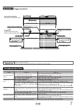
❶
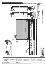
Place a 10 mm support under the door.
❷
While holding the door, place the groove under the door
on the protruding part of the
ÀRRUJXLGH
Roller
(
holder
)
Roller
(
main body
)
CLICK
Support 10
mm
(
To be removed
after hanging
)
⑥
Floor guide
protruding part
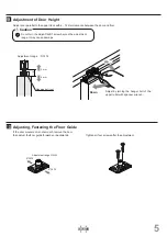
Fastening of Additional Trigger
6
Fasten trigger to the hole made during procedure with provided screws.
The jig makes it easy to install the trigger.
●
Align trigger with the
holes.
●
Turn the jig 90
゚
and fix
the trigger.
●
Remove the jig.
●
Assemble trigger to jig.
1
2
1
3
4
Trigger assembly
OK
Out of straight
Correct installation
Trigger
Jig
2
×
I
4.5
30
Screws
Screwdriver (+)
90°
Correct installation
Out of straight
OK
90°
Floor guide
44
18
7
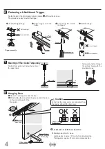
Mounting of Floor Guide Temporarily
Hanging Door
8
3RVLWLRQÀRRUJXLGHMXVWEHORZWKHFHQWHURI
the upper track.
Temporarily fasten through
the slotted holes with the
provided screws.
❶
❷
❸
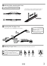
9HUL¿FDWLRQRI6RIW&ORVHU2SHUDWLRQ
●
Starting point of soft - close.
Leading edge : approx. 100 mm before closed position.
Trailing edge : approx. 50 mm before closed position.
Verify that the main unit is not dislocated from
the casing, either of the door ends.
Lever is on
the bottom.
Caution
OK


