lamber M115 Instruction Manual Download Page 30


30 

WATER CONNECTIONS 

 
Carefully comply with any national or 
regional regulations in force. 


Hot water supply 


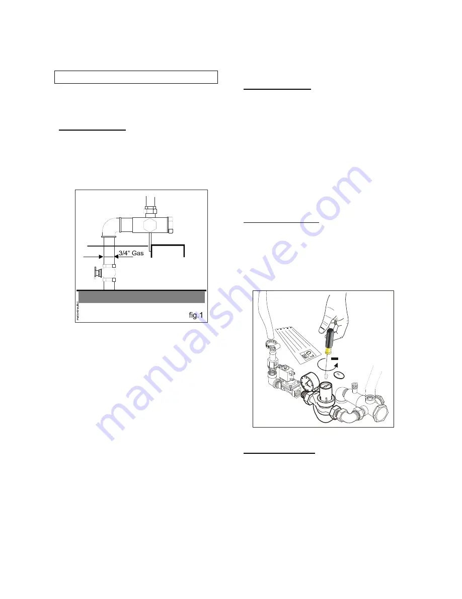
Arrange a gate valve in an easily 
accessible place, with a tap having a 
3/4"gas thread spout at its end and connect 
to the water inlet valve (fig.1) 


-


temperatur

 between 55° and 60°C,   

-


Dynamic Pressure

 2÷4 bar (200÷400 

kPa),  

-


Hardness 

between 

7,2 and 12,5 °F


N.B.:

  Each machine is equipped with a 

pressure reducer. In order to obtain an 
excellent rinsing, it shall be calibrated 
according to the data reported on the plate 
located in connection with the reducer 
itself. 


N.B.:

  Each machine is equipped with a 

pressure reducer near the water inlet 
valves. 
In order to obtain an optimum rinse it is 
necessary to adjust it from 0,6 to 1 bar 
according to inlet water pressure and 
temperature. 

(remember that the required dynamic 
pressure must be 2÷4 bar (200÷400kPa) 
and that inlet water temperature must be 
55÷60°C for standard machines). 

 
If a variation of rinse pressure is required 
while installing, proceed as follows: 
1: make the machine work and check that  
the rinse is activated;  
2: Take away the upper protection plug on 
the reduction gear and turn the proper 
adjusting screw anti-clockwise in order to 
decrease pressure or clockwise in order to 
increase it or to restore the optimum 
working conditions (see picture 1A). 


PIC.1A- PRESSURE REDUCER


Cold water supply 
 

This connection is required only for 
machine with 

steam condenser .


Water shall be supplied at a temperature 
ranging from 10÷15°C and at a dynamic 
pressure of 2÷4 bar (200÷400 kPa). 
 

Summary of Contents for M115

Page 1: ...DISHWASHERS WITH PULL THROUGH RACK INSTRUCTIONS MANUAL M115 R06 2012...

Page 2: ......

Page 3: ...l appliances for households and similar purposes electric tools and similar electric apparatus EN 55014 1 1 2006 A1 2009 Limits for harmonic current emissions equipment input current 16 A per phase EN...

Page 4: ...to separate waste collection it must be disposed of at appropriate waste collection points or returned to the distributor against purchase of new equipment of similar type or having the same functions...

Page 5: ...5 WASHING RINSING M O D E L M O D E L M115 left right M115 right left...

Page 6: ...IMER SPLASH SHIELD PMC PMA PMA R BOOSTER PUMP Motor kW TECHNICAL SPECIFICATIONS Model version Left Right Right Left 1st speed baskets hour 2nd speed baskets hour ELECTRIC POWER kW ELECTRICAL INPUT A E...

Page 7: ...less steel autodraining washing pump Counterbalanced door Front panel composition Main ON OFF switch Start pushbutton Stop pushbutton Emergency pushbutton Machine ON indicator Machine ready indicator...

Page 8: ...Achievements page 21 Safety devices page 21 Washing flow control system page 23 Useful hints of stainless steel maintenance page 24 2 INSTRUCTIONS FOR THE INSTALLER page 25 Installation page 26 Secon...

Page 9: ...AL NORMS ENGLISH Tank You for purchasing our Dishwashing Machine Perfect washing up results as far as hygiene concerns and a correct operation of the dishwashing machine can be assured only in case th...

Page 10: ...h inferior to 130dB C PRELIMINARY OBSERVATION Carefully read the instructions reported in the present user manual as it gives important indications about safety of installation operation and maintenan...

Page 11: ...or lifting the machine care must be taken to comply with all the relevant regulations governing such operations installation should be carried out by qualified personnel according to the manufacturer...

Page 12: ...electrical components are integral TRANSPORT AND INSTALLATION To lift and transport the machine insert the truck forks under the frame connected to the points indicated by the yellow adhesives applied...

Page 13: ...INSTRUCTIONS FOR THE USER...

Page 14: ...c dispenser with feeler for the measurement of the detergent concentration because brownish spots can form on the surfaces due to chlorine reactions when pouring the detergent directly into the tank I...

Page 15: ...c acid In order to avoid damage to the machine do not increase the quantities and once operations end rinse abundantly HYGIENE At last each 30 days it would be useful to do this operation which guaran...

Page 16: ...off switch P to start up the machine The lamp G will start flashing and the tanks filling will automatically start Lamp G lighted on indicates that the appropriate level has been reached in the tank...

Page 17: ...er the pushbutton has been rotated and released The machine is equipped with a valve for the automatic drain At the end of the washing operations press button I STOP check that the switch P is in posi...

Page 18: ...onitor the levels of the detergent and the rinse agent liquid in the respective containers 3 Remove the filters periodically and remove any residues therefrom it is suggested to buy another spare filt...

Page 19: ...19 BASKETS cestelli m115 GB cdr PP12 18 G8 CVA option TAKE CARE BASKETS WITH DISHES OR TRAYS MUST BE PUT INTO THE WASHING TUNNEL AS SHOWN IN THE PICTURE M115 CB...

Page 20: ...e pre wash if any and wash them carefully every day don t beat them against the floor or others 6 When the tanks are empty remove and wash the slide filters and the suction pump filters 7 Remove and w...

Page 21: ...nditions it is advisable to carry out periodical sanifications and scale removing operations ACHIEVEMENTS Any deficiency in the washing process is apparent when dirty residuals are visible Any halos m...

Page 22: ...see the relevant chapter included in the second part of the manual dedicated to the installer MOTOR PROTECTION DEVICES Each motor is protected against short circuits and current overload by automatic...

Page 23: ...o reduce the washing jet power This device is placed into the pre washing and washing areas of the rack conveyor dishwashing machines by the lower washing arms group In order to act on the control sys...

Page 24: ...exterior panelling upper tops tanks etc Comply with the following instructions when cleaning and servicing parts in stainless steel Ordinary daily maintenance Carefully and frequently clean the surfac...

Page 25: ...e following instructions are addressed to a qualified personnel the only one authorised to carry out checks and repair if any The Manufacturer declines any responsibility in the case of interventions...

Page 26: ...26...

Page 27: ...f you use chlorinated sanitizers it is always advisable to employ an automatic dispenser provided with feeler for the measurement of the detergent concentration because brownish spots can form on the...

Page 28: ...r electric box standard M115 model or the blue terminals into the upper electric box M115 with drying tunnel marked by special tags Note In order to let cables pass please use the labelled wire clamp...

Page 29: ...e current drawn by the machine The system must also be provided with a proper ground lead in accordance with the existings norms The electric cable must be of the following type H07RN F For a correct...

Page 30: ...an optimum rinse it is necessary to adjust it from 0 6 to 1 bar according to inlet water pressure and temperature remember that the required dynamic pressure must be 2 4 bar 200 400kPa and that inlet...

Page 31: ...indicated in the installation drawings In order to make the equipment independent from the general steam distribution network it is necessary to use gate and gas on off valves see draw 2 and 3 This ty...

Page 32: ...pumps is correct Should the pumps rotate in the reverse direction reverse two wires of the line Make a number of empty racks to pass through then check that water jets are sprinkled fron the rinsing n...

Page 33: ...witch the machine off 2 Remove the protection panel 3 Load the machine with baskets full of dishes to be washed 4 Loose the axial ring nut with the hexagon ring wrench type A 5 Disengage the friction...

Page 34: ...es out of the vapour condensing cap Generally it is sufficient to slightly open the valve ATTENTION An excessive opening can cause the cooling of the tank V Desc lav DES CVMREGOL 2012 WASHING AUTOTIME...

Page 35: ...effective and calibrated B Check that the overflows are in their housing C Check that the solenoid valve EV2 is effective and gets tension 4 The racks don t step up A Check that nothing is resting on...

Page 36: ...g arms are not clogged If necessary clean them D Check that the dishes are placed in the respective racks Soup plates have to be mandatorily placed in rack type P12 16 E Check that the temperatures in...

Page 37: ...ozzles are not clogged by calcareous residuals and they are oriented to the right direction C Water inlet solenoid valve EV1 operates correctly D The water input filter is not clogged E Energy saver m...

Page 38: ...e air suction holes located on the upper panel are not clogged by foreign bodies C The Overload cutout is not triggered If so restore it This drawback is displayed by lamp M LS3 being ON D Fuses and r...

Page 39: ...are not broken E Check that motor M08 is not blocked nor burnt and rotates in the right direction F Check that the cold water feed cock is open and water is present at a pressure of at least 2 bars G...

Page 40: ...KING OF THE MACHINE PUMPS FANS ETC PLEASE CHECK THAT THE INSIDE THE MACHINE FIG A TURNS ANTICLOCKWISE OR THAT THE SHAFT UNDER THE WASHING TANK FIG B TURNS IN THE DIRECTION INDICATED BY THE YELLOW ARRO...

Page 41: ...41 TABLE CONNECTION SCHEME MURO MUR WALL WAND Piano di lavoro plan de travail work table Arbeitstisch...

Page 42: ...42...

Reviews: