background image


Important Safety Instructions 

 
Before  using  this  equipment  read  all  manuals  and  other  documents  related  to  this  unit  and  other  equipment 
connected to this unit.  Always have a copy of a units manual on file nearby, in a safe place; if a replacement 
copy of a manual is needed it can be found at the www.lamarchemfg.com. 

Electrical Safety 


WARNING:

  Hazardous  Voltages  are  present  at  the  input  of  power  systems.    The  output  from 

rectifiers  and  from  batteries  may  be  low  in  voltage,  but  can  have  a  very  high  current  capacity  that 
may cause severe or even fatal injury. 
 

When working with any live battery or power system, follow these precautions: 


Never work alone on any live power system; someone should always be close enough to come to your aid. 


Remove personal metal items such as rings, bracelets, necklaces, and watches. 


Wear complete eye protection (with side shields) and clothing protection. 


Always wear gloves and use insulated hand tools. 


WARNING:

 Lethal Voltages are present within the power system.  Parts inside the unit may still be 

energized even when the unit has been disconnected from the AC input power.  Check with a meter 
before proceeding. Do not touch any uninsulated parts. 


A licensed electrician should be used in the installation of any unit. 


Always disconnect the unit from the supply, batteries and loads before performing maintenance or cleaning. 


If the unit is hot-swappable, simply remove it from the shelf for any maintenance or cleaning.  


Always assume that an electrical connection is live and check the connection relative to ground. 


Be sure that neither liquids nor any wet material come in contact with any internal components. 


Do not operate this unit outside the input and output ratings listed on the unit nameplate. 


Do not use this unit for any purpose not described in the operation manual. 


Mechanical Safety 


This unit or parts of the unit may get very hot during normal operation, use care when working nearby. 


Do not expose equipment to rain or snow.  Always install in a clean, dry location. 


Do not operate equipment if it has received a sharp blow, been dropped, or otherwise damaged in any way. 


Do not disassemble this unit. Incorrect re-assembly may result in a risk of electric shock or fire. 


Battery Safety 


WARNING:

 Follow all of the battery manufacturer’s  safety recommendations when working with or 

around  battery  systems.  DO  NOT  smoke  or  introduce  a  spark  or  open  flame  in  the  vicinity  of  a 
battery.  Some batteries generate explosive gases during normal battery operation. 


To reduce risk of arc, connect and disconnect the battery only when the unit is off. 


If it is necessary to remove battery connections, always remove the grounded terminal from the battery first. 


Remove personal metal items such as rings, bracelets, necklaces, and watches. 


Always wear rubber gloves, safety glasses, and a rubber lined vest/apron when working near a battery. 


Have plenty of fresh water and soap nearby in case the battery electrolyte contacts skin, clothing, or eyes. 


If the battery electrolyte contacts skin or clothing, wash immediately with soap and water.   


If  the  electrolyte  enters  the  eye,  immediately  flood  the  eye  with  running  cold  water  for  at  least  ten  (10) 
minutes and seek medical attention immediately. 


Do not drop metal on a battery.  A spark or short-circuit could occur and could cause an explosion.  


Summary of Contents for A75D

Page 1: ...Des Plaines IL 60018 1967 CPN 129767 Instruction Drawing Number P25 LA75D A75DE 3 Tel 847 299 1188 Fax 847 299 3061 Revision A00 Rev Date 07 14 ECN 20494 Installation and Operation Manual La Marche Manufacturing Company www lamarchemfg com A75 A75 A75 A75D D D D A75DE A75DE A75DE A75DE Single Phase SCR Filtered Charger Battery Eliminator ...

Page 2: ......

Page 3: ... that neither liquids nor any wet material come in contact with any internal components Do not operate this unit outside the input and output ratings listed on the unit nameplate Do not use this unit for any purpose not described in the operation manual Mechanical Safety This unit or parts of the unit may get very hot during normal operation use care when working nearby Do not expose equipment to ...

Page 4: ... to any damage before installing the product Verify that you have all the necessary parts per your order for proper assembly CAUTION Failure to properly file a claim for shipping damages or provide a copy of the claim to La Marche may void warranty service for any physical damages reported for repair Returns for Service Save the original shipping container If the product needs to be returned for s...

Page 5: ...ing the A75D E 4B75 475 Only 5 2 1 2 Floor Mounting the A75D E All Cases 6 2 1 3 Rack Mounting the A75D E 7 2 2 Changing Transformer Taps 8 2 3 Making the AC Input Connections 9 2 4 Making the DC Output Connections 10 2 5 Alarms 11 2 5 1 Standard Alarms 11 2 5 2 Understanding the Alarms 12 2 5 3 Discrete Alarm Relay Board Option 46R 14 2 5 4 Alarm Connection Procedure 15 2 6 Installing External Te...

Page 6: ...arm Settings 26 3 4 7 Communications Settings 27 3 4 8 Set Clock 27 3 4 9 Data Logging 28 3 4 10 LCD Settings 28 3 4 11 Security 28 3 4 12 Saving Settings 28 3 5 Test Menu 29 3 5 1 Test LEDs 29 3 5 2 Test Relays 29 4 Data Logging 30 4 1 Events Only Logging 30 4 2 Interval Logging 30 4 3 Installing Removing the SD Card 30 4 4 Reading the Log File 30 5 Service 31 5 1 Performing Routine Maintenance 3...

Page 7: ...ring Connection 17 Figure 12 Remote Equalize Connections 18 Figure 13 Ground Detection Connections 19 Figure 14 A75D E Front Panel 21 Figure 15 Example Events Log 30 Table 1 Case Type and Weight 6 30 ADC 3 Table 2 Case Type and Weight Table 35 100 ADC 3 Table 3 Available mounting methods for each of the A75D E case sizes 4 Table 4 Available Rack Mount Configurations 7 Table 5 Input Terminal Connec...

Page 8: ...ient temperature range The A75D E series is offered with DC output voltages of 24 48 or 130VDC with output currents from 6 to 100 Amps These chargers may be powered with 120 208 240 or 480VAC Understanding the Model Number The A75D E model number is coded to describe the options that are included Find the model number on the nomenclature nameplate of the charger Then follow the chart to determine ...

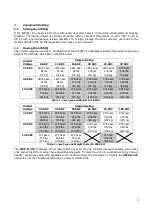
Page 9: ...190 lbs 38 kg 44 kg 62 kg 72 kg 73 kg 86 kg 130 VDC 475 Case 475 Case 475 Case 475 Case 475 Case 475 Case 178 lbs 185 lbs 191 lbs 235 lbs 255 lbs 300 lbs 81 kg 84 kg 87 kg 107 kg 116 kg 137 kg Table 1 Case Type and Weight 6 30 ADC Output Voltage Ampere Rating 35 ADC 40 ADC 50 ADC 60 ADC 75 ADC 100 ADC 24 VDC 475 Case 475 Case 475 Case 475 Case 975 Case 975 Case 150 lbs 160 lbs 185 lbs 208 lbs 240 ...

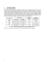
Page 10: ...d away from drips and splatter The A75D E utilizes convection cooling so a clearance of at least 6in 152mm of free air must be maintained on the top bottom and both sides for cooling air Maintain 36in 914mm or more of clearance at the front of the charger in order to allow for operation and maintenance Case Number Cable Entry Standard Mounting Optional Mounting Kits AC Input DC Output 4B75 Right T...

Page 11: ...the A75D E install four 0 25 in 6 4 mm bolts on the wall rated to support the charger weight plus a safety factor of at least two times for the 475 case 6 bolts are needed Place the A75D E on the bolts add appropriate mounting hardware and tighten Refer to the figures below for mounting dimensions and specifications NOTE All above dimensions are in inches For further A75D E cabinet information see...

Page 12: ... 2 mm to the overall height of 4B75 and 475 cases 975 and 72 cases include the height of the bracket in their overall height Floor Mounting Procedure To floor mount the A75D E install four 0 25in 6 4mm bolts into the floor Place the A75D E on the bolts add appropriate mounting hardware and tighten securely The images below show the footprint of each A75D E case style A B 4B75 15 5 11 219 475 975 1...

Page 13: ...ntrances and be sure the knockouts on the sides or bottom of the charger are accessible after the charger is rack mounted The table and figure below shows rack mounting options for A75D E Rack Mounting Procedure To rack mount the A75D E first mount the unit onto the rack mounting brackets using the hardware supplied Second install the brackets onto the rack Provide at minimum 6in 152mm of air spac...

Page 14: ...ing page NOTE An A75D E battery charger rated for 480 VAC or 600 VAC input uses a special transformer that has no taps The 480 VAC and 600 VAC transformers cannot be used for any other input voltage Changing Transformer Taps Procedure Before beginning any work inside the charger enclosure ensure that all incoming AC supply and DC load wires are de energized Verify that no voltage is present inside...

Page 15: ...ECTION MINIMUM 1 14 14 3 14 14 4 14 14 5 14 14 6 14 14 10 14 14 15 12 12 20 12 12 25 10 12 30 10 10 35 8 10 40 8 10 45 8 10 50 8 10 60 6 10 70 6 8 80 4 8 90 4 8 100 4 8 110 2 6 125 2 6 130 2 6 140 1 6 Table 6 Wire Size Minimum Requirements NOTE These are recommended sizes All National and Local Wiring Codes must be followed AC Connection Procedure First connect an adequate earth ground lead use ta...

Page 16: ...ating Current Carrying Capacity of Wire K LF AVD CMA MaxAmp DC Connection Procedure To prevent the DC circuit breaker from tripping when connecting the battery connections should be done in the following order 1 Turn off the unit s AC and DC circuit breakers 2 Connect AC line to the unit s input terminals as described in Section 2 3 Making the AC Input Connections 3 Connect the battery cables to t...

Page 17: ...ge Positive Ground High DC Voltage Negative Ground Low DC Current End of Discharge AC Fail Overload Current Limit Optional to include in Summary alarm Customer Calibration If an alarm condition occurs for a default time of longer than 5 seconds the summary alarm relay will activate The AC Fail alarm is default set to trigger after 20 seconds When an alarm activates the specific indicator on the fr...

Page 18: ...harger component If the high DC voltage shut down alarm activates the DC output of the charger shuts off to prevent irreversible damage to the battery This alarm will stay latched until the unit is reset by isolating from all power sources See Section 3 4 Settings Menu for information on viewing and adjusting the threshold value The HIGH DCV ALARM will trigger if the output DC voltage rises above ...

Page 19: ...adjusting the current limit threshold value When the unit is in overload the same red Overload Current Limit indicator LED will turn on solid The overload threshold is not adjustable All alarms have adjustable time delays to energize the range is 0 through 255 seconds Refer to Table 11 for the factory setting of each alarm Alarm Delay seconds AC Fail 20 Low DC Voltage 5 End of Discharge 5 EQ Timer...

Page 20: ... Alarm Form C Contact Ratings All alarms contacts for the A75D E are designed to be fail safe In other words if both the AC and DC power are removed each alarm will be indicating in its correct state To accomplish this certain alarm relays are de energized on failure such as AC Failure and certain alarm relays are energized on failure such as High DCV All relay contacts are shown in the de energiz...

Page 21: ...e example shown in Figure 9 demonstrates how a customer might connect the AC failure contacts The AC failure relay is de energized on alarm so the Speaker and the Red Lamp connected to the Normally Closed contacts will activate under the AC failure condition The Green Lamp connected to the Normally Open contacts will be active when AC power is present effectively acting as an external AC on Lamp A...

Page 22: ...tion circuit and a 24 foot long temperature probe Option 11Y includes the compensation circuit and a 100 foot long temperature probe With either option approximately two feet of the probe is taken inside the charger enclosure 2 6 1 External Probe Connection Procedure Before making any connections to the A75D E ensure that the AC Power is off at the main breaker box and that both of the unit s brea...

Page 23: ... to the Load Share Enable terminal of the second charger Repeat if using more than two chargers This connection can be made with a 16 AWG wire 5 Turn on all chargers 6 Wait for batteries to become fully charged and or loads to stabilize Check each unit for equal load sharing Minor voltage increases can be made to unit carrying lesser load 2 7 2 Load Sharing Procedure with Batteries Loads 1 Connect...

Page 24: ... are not required 1 Turn off all chargers 2 Connect the Load Sharing Terminal using Section 2 7 1 or 2 7 2 above 3 Connect CANbus terminal J2 Pins 1 2 3 of Charger 1 to the CANbus terminal J2 Pins 4 5 6 of Charger 2 This connection can be made with a 16 AWG wire 4 If using more than two chargers CANbus can be chained Connect CANbus terminal J2 Pins 1 2 3 of Charger 2 to the CANbus terminal J2 Pins...

Page 25: ...ore precision system is needed many systems that are designed specifically for ground detection are compatible with the La Marche battery chargers If the battery or loads are either positively or negatively grounded it is recommended that ground detection be disabled If the system is know to be grounded and the ground detection is enabled the charger will show a ground fault at all times Ground De...

Page 26: ...alve Regulated Lead Acid NC Nickel Cadmium 3 1 1 Checking the Installation Before attempting to start up the A75D E check and verify that all connections are correct Check that all terminations and contacts are tightened securely Check that the transformer is set for the correct voltage and that the input frequency matches the nameplate or the charger Check that the battery load voltage matches th...

Page 27: ...e membrane The parameters that can be displayed sequence assuming only the down arrow is being used are as follows System DC Output Temperature Compensation Status Charger AC Input Unit Clock Date and Time Logging Status Equalize Timer Status and Length Temperature of SCR Heatsink Auto Equalize Countdown Internal External Probe Temperature Selected Equalize Timer Mode Voltage 130 8 V Current 19 1 ...

Page 28: ...rs by default and can be changed via Customer Calibration After the timer cycles to zero the charger will automatically return to the float mode Equalize mode will not start again until it is manually activated by the user Mode 1 7 Day Auto EQ Mode 1 is an automatic equalize cycle that activates every seven days The length of the equalize cycle is determined by the timer setting The length of the ...

Page 29: ...ctions are included as part of the manual package only if a communications option has been ordered 3 4 1 Set to Defaults The first option in the settings menu is Set to Defaults This option resets all customer adjustable settings to the factory defaults It is important to note that the factory defaults are not necessarily the correct settings for the specific DC system Before the charger is shippe...

Page 30: ...nfig in the Save Load Confg menu If a configuration file already exists it will be overwritten In order to prevent data loss the Remove Drive option must be selected before physically removing the memory card Select Remove Drive in the Save Load Confg menu and then physically remove the Micro SD card from the S2A 368S card 3 4 4 Output Settings The output settings menu allows the customer to adjus...

Page 31: ...ode determines when the charger will go into an equalize charging cycle The timer modes are Auto EQ OFF 7 Day Auto EQ 14 Day Auto EQ 30 Day Auto EQ and Auto EQ on LV The default setting for the equalize timer mode is Auto EQ OFF The Equalize Timer Modes are discussed in further detail in Section 3 3 1 Equalize Timer Modes Remote Equalize Remote equalize enables two chargers connected in parallel t...

Page 32: ...which an alarm triggers The threshold can be changed for High Voltage Shutdown AC Failure Low DC Current Low Voltage Alarm Reset Low Voltage End of Discharge Reset End of Discharge and High Voltage Alarm threshold defaults above are based on a 60L charger output The alarm threshold values shown above are not representative of the default values for all A75D E chargers 3 4 6 2 Alarm Delays The Alar...

Page 33: ...The HVSD alarm latches by default and cannot be changed 3 4 7 Communications Settings Upon selecting communications settings the user will be given access to the following Modbus settings The default values are show in the illustration all customer options are listed to the right of each option below If the charger is equipped with an optional communications card refer to the communications instru...

Page 34: ...d to enter calibration By default the password is disabled Upon selecting Password Enable the user will be prompted to set a new password or enter an existing password The password is a four digit pin If the password is enabled the four digit pin must be entered in order to access the settings menu The Set Password option allows to create a four digit pin or change the existing one If a password i...

Page 35: ...functionality of the alarm relay contacts The menu allows for each contact to be tested individually or all at once When a relay is being tested its contacts will change state This means if a relay is in alarm state it will revert to the non alarm state during relay testing When an alarm relay is being tested the corresponding LED on the membrane will change state There is no relay contacts for th...

Page 36: ...ore installing or removing the SD card ensure that the AC Power is off at the main breaker box and that all of the units breakers are off Verify that no voltage is present by using a voltmeter at all input and output terminals 4 4 Reading the Log File The data log file is written as events csv There may be other files written to the SD card as well but the events and or interval logging is written...

Page 37: ...er inverter with a low pressure air hose 2 Make sure all connections are tight 3 Perform a visual check on all internal components 4 Check front panel meters and alarms for accuracy 4th Year REPEAT ABOVE WITH THE ADDITION OF 1 Check relay contacts for pitting or corrosion 2 Check capacitors for leakage 7th Year REPEAT ALL WITH THE ADDITION OF 1 Filter and resonating capacitors should be replaced 1...

Page 38: ...ive batteries and customer loads make sure batteries and loads are free from defects NOTE If the problem is found to be located in the printed circuit boards the board should be replaced No attempt should be made to repair circuit boards in the field When calling in for a service inquiry or for troubleshooting assistance be sure to have all of the following information on hand 1 Equipment model nu...

Page 39: ...ive Shunt Defective Control Card S2A 368 Unit Running Hot Inadequate Ventilation Ambient is Too Hot Battery Temperature Too High Insufficient Cool Down Between Charges Battery Power Demand Too Great Battery Needs to be Equalized Erratic Operation Defective Control Card S2A 368 Incorrect Damaged or Loose Cable Harness Connections Defective Component on Heatsink Assembly Moisture Inside Cabinet Lack...

Page 40: ...1 2840 501 1711 6 48 3 418 355 63 214 12 48 6 835 710 125 428 16 48 8 1114 947 167 570 20 48 10 1392 1183 209 713 25 48 12 1670 1420 251 856 30 48 15 2088 1775 313 1069 35 48 17 2366 2011 355 1212 40 48 20 2784 2366 418 1426 50 48 24 3341 2840 501 1711 60 48 29 4037 3431 606 2068 75 48 37 5150 4378 773 2638 100 48 49 6821 5798 1023 3493 6 130 7 974 828 146 499 12 130 15 2088 1775 313 1069 16 130 2...

Page 41: ... service arrangements Should minor adjustments be required the local La Marche sales representative should be contacted to provide this service only All sales are final Only standard LaMarche units will be considered for return A 25 restocking fee is charged when return is factory authorized Special units are not returnable In no event shall La Marche Manufacturing Co have any liability for conseq...

Page 42: ...36 Appendix C Document Control and Revision History Part Number 129767 Instruction Number P25 LA75D A75DE 3 Issue ECN 20494 7 14 ...

Reviews: