
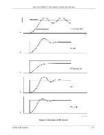

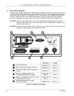
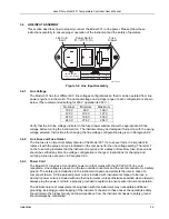
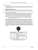


Lake Shore Model 331 Temperature Controller User’s Manual
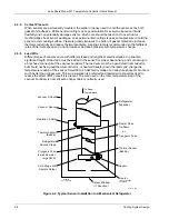
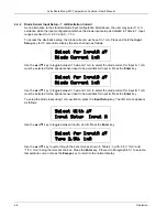
3.5.5
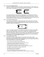
Four-Lead Sensor Measurement
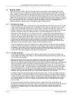
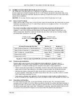
All sensors, including both two lead and four lead can be measured with a four lead technique. The
purpose of a four lead measurement is to eliminate the effect of lead resistance on the measurement.
If it is not taken out, lead resistance is a direct error when measuring a sensor.
I+
V+
I
V
Four-Lead
Diode
Four-Lead
Platinum
I+
V+
I
V
In a four lead measurement, current leads and voltage leads are run separately up to the sensor.
With separate leads there is little current in the voltage leads so their resistance does not enter into
the measurement. Resistance in the current leads will not change the measurement as long as the
voltage compliance of the current source is not reached. When two lead sensors are used in four lead
measurements, the short leads on the sensor have an insignificant resistance.
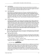
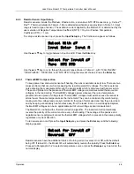
3.5.6
Two-Lead Sensor Measurement
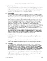
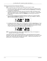
There are times when crowding in a cryogenic system forces users to read sensors in a two lead
configuration because there are not enough feedthroughs or room for lead wires. If this is the case,
plus voltage to plus current and minus voltage to minus current leads are attached at the back of the
instrument or at the vacuum feedthrough.
I+
V+
I
V
Two-Lead
Diode
The error in a resistive measurement is the resistance of the lead wire run with current and voltage
together. If the leads contribute 2 or 3
Ω
to a 10 k
Ω
reading, the error can probably be tolerated.
When measuring voltage for diode sensors the error in voltage can be calculated as the lead
resistance times the current, typically 10 µA. For example: a 10
Ω
lead resistance times 10 µA results
in a 0.1 mV error in voltage. Given the sensitivity of a silicon diode at 4.2 K the error in temperature
would be only 3 mK. At 77 K the sensitivity of a silicon diode is lower so the error would be close to
50 mK. Again, this may not be a problem for every user.
3.5.7
Lowering Measurement Noise
Good instrument hardware setup technique is one of the least expensive ways to reduce
measurement noise. The suggestions fall into two categories: (1) Do not let noise from the outside
enter into the measurement, and (2) Let the instrument isolation and other hardware features work to
their best advantage. Here are some further suggestions:
• Use four-lead measurement whenever possible.
• Do not connect sensor leads to chassis or earth ground.
• If sensor leads must be grounded, ground leads on only one sensor.
• Use twisted shielded cable outside the cooling system.
• Attach the shield pin on the sensor connector to the cable shield.
• Do not attach the cable shield at the other end of the cable, not even to ground.
• Run different inputs and outputs in their own shielded cable.
• Use twisted wire inside the cooling system.
• Use similar technique for heater leads.
• Use a grounded receptacle for the instrument power cord.
• Consider ground strapping the instrument chassis to other instruments or computers.
3-6
Installation


