


Lake Shore Model 331 Temperature Controller User’s Manual
8.5
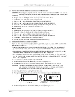
TOP OF ENCLOSURE REMOVE AND REPLACE PROCEDURE
WARNING:
To avoid potentially lethal shocks, turn off controller and disconnect it from AC power line
before performing this procedure. Only qualified personnel should perform this procedure.
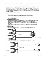
REMOVAL
1. Set power switch to Off (
O
) and disconnect power cord from rear of unit.
2. If attached, remove 19-inch rack mounting brackets.
3. Use 5/64 hex key to remove four screws attaching top panel to unit.
4. Use 5/64 hex key to loosen two rear screws attaching bottom panel to unit.
5. Carefully remove the back bezel by sliding it straight back away from the unit.
6. Slide the top panel back and remove it from the unit.
INSTALLATION
1. Slide the top panel forward in the track provided on each side of the unit.
2. Carefully replace the back bezel by sliding it straight into the unit.
3. Use 5/64 hex key to install four screws attaching top panel to unit.
4. Use 5/64 hex key to tighten two rear screws attaching bottom panel to unit.
5. If required, reattach 19-inch rack mounting brackets.
6. Connect power cord to rear of unit and set power switch to On (
l
).
8.6
FIRMWARE AND NOVRAM REPLACEMENT
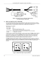
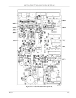
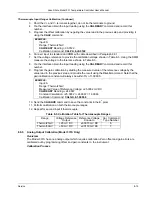
There are three integrated circuits (ICs) that may potentially require replacement. The location of the
ICs is shown in Figure 8-7.
• Input Microcontroller (U16) – Contains software that configures the inputs, takes readings, and
performs control functions. Has a sticker on top labeled “M331IF.HEX” and a version number.
• Main Firmware Erasable Programmable Read Only Memory (EPROM) (U22) – Contains the user
interface software. Has a sticker on top labeled “M331F.HEX” and a date.
• Non-Volatile Random Access Memory (NOVRAM) (U23) – Contains instrument settings and user
curves. The NOVRAM is replaced when the customer purchases a Model 8002-05-331 CalCurve™.
Refer to Paragraph 7.2.
Use the following procedure to replace any of these ICs.
1. Follow the top of enclosure
REMOVAL
procedure in Paragraph 8.5.
2. Locate the IC on the main circuit board. See Figure 8-7. Note orientation of existing IC.
CAUTION:
The ICs are Electrostatic Discharge Sensitive (ESDS) devices. Wear shock-proof
wrist straps (resistor limited to <5 mA) to prevent injury to service personnel and to
avoid inducing an Electrostatic Discharge (ESD) into the device.
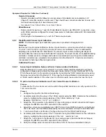
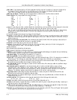
3. Use IC puller to remove existing IC from the socket.
4. Noting orientation of new IC, use an IC insertion tool to place new device into socket.
1
Match notch on
IC to notch
in socket
Typical IC
Typical NOVRAM
DALLAS
xxxxxxxxx
xxxxxxxxx
1
Match notch on
NOVRAM to notch
in socket
Eprom.eps
5. Follow the top of enclosure
INSTALLATION
procedure in Paragraph 8.5.
Service
8-7


