


Lake Shore Model 331 Temperature Controller User’s Manual
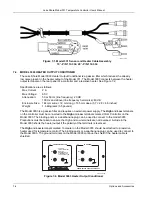
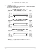
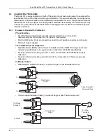
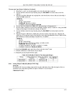
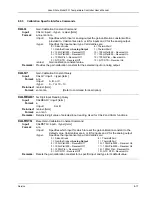
Terminal Block Connector
Lake Shore P/N 106-739
1
2 3
4 5
6 7 8
Use screwdriver to
lock or unlock wires
Insert wire
into slot
Slides into slot at
rear of Model 331
C-331-8-4.eps
Pin Description
1
2
3
4
5
6
7
8
Relay 1 – Normally Closed (NC)
Relay 1 – Common (COM)
Relay 1 – Normally Open (NO)
Relay 2 – Normally Close (NC)
Relay 2 – Common (COM)
Relay 2 – Normally Open (NO)
Analog Voltage Output – Hi (+)
Analog Voltage Output – Lo (–)
Figure 8-4. RELAYS and ANALOG OUPUT Terminal Block
1
2
3
4
5
6
7
8
9
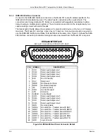
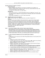
RS-232 (DTE)
F-331-8-5.eps
Model 331 Temperature Controller
Typical Computers
DE-9P (DTE)
DB-25P (DTE)
DE-9P (DTE)
Pin Description Pin
Description
Pin
Description
1
No Connection
2
TD (out)
1
DCD (in)
2
Receive Data (RD in)
3
RD (in)
2
RD (in)
3
Transmit Data (TD out)
4
RTS (out)
3
TD (out)
4
Data Terminal Ready (DTR out)
5
CTS (in)
4
DTR (out)
5
Ground (GND)
6
DSR (in)
5
GND
6
Data Set Ready (DSR in)
7
GND
6
DSR (in)
7
Data Terminal Ready (DTR out) (tied to 4)
8
DCD (in)
7
RTS (out)
8
No Connection
20
DTR (out)
8
CTS (in)
9
No Connection
22
Ring in (in)
9
Ring in (in)
Figure 8-5. RS-232 Connector Details
8-4
Service


