background image

Lake Shore Model 321 Autotuning Temperature Controller User’s Manual 


3-14 

Operation 


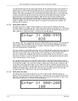
Press 

Enter

 to accept the new ramp rate. You will now return to the normal display. Now press the 

Setpoint

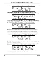
 button and use the numeric keypad to enter 100 K. You should see the following display. 


The normal display returns showing the old setpoint of 50 K. The display slowly begin to change to 
100 K at a rate of 1 K per minute, reaching 100 K in 50 minutes. The ramp can be stopped at the 
current setpoint by pressing 

Setpoint

 and then 

Enter

. To turn off the ramping feature, press the 

Ramp Rate

 button and use either the 

s

t

, or 

Ramp Rate

 button to cycle the selector arrow (

) to 

no, then push 

Enter

3.3.4 Autotune 

There are five tuning modes on the Model 321: Auto P, Auto PI, Auto PID, Manual, and Zone. This 
paragraph will discuss the three Autotune modes. The Autotuning algorithm determines the proper 
settings for Gain (

P

roportional), Reset (

I

ntegral) and Rate (

D

erivative) by observing the time response 

of the system upon changes in setpoint under either P, PI or PID control. 


Adaptation of an autotuning algorithm for use at cryogenic temperatures is a more complex issue 
than for more stable, well-behaved, high-temperature loads. For example, over its useful temperature 
range a single cryogenic load may exhibit thermal property variations of three orders of magnitude or 
greater. 


The Autotuning function is initiated with a change in temperature setpoint. The controller 
automatically gathers data to determine optimum control parameters. No more tuning will be done 
until the next change in setpoint. The controller will never disturb the system. It tunes only on user 
setpoint changes. 


System design is also a factor. Under some circumstances, very fast cryogenic systems may not 
provide sufficient data points on step changes to accurately predict the proper control settings. 
Unusually large thermal lags, caused by poor placement and mounting relative to the heater, can 
obstruct the correlation between the heater and the system necessary to tune properly. 


For slower systems with longer time constants, which are very difficult to tune manually, Autotuning 
can obtain enough information on a step change to characterize the system and determine proper 
values for Gain, Reset, and Rate. 


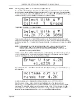
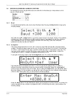
To put the controller in Autotune PID mode, press the 

AutoTune

 button, and press either the 

s

t

or 

AutoTune

 button to cycle the selector arrow (

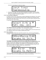
) to Auto PID. You should see the following 

display. 


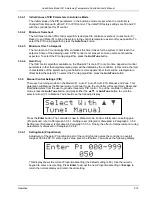
Press the 

Enter

 button. The controller is now in Autotuning PID mode. The method for setting the 

controller to Auto P or Auto PI modes is the same as just explained. Further information on Auto P, I, 
and D settings are provided in the following paragraphs. 

Summary of Contents for 321-01

Page 1: ...tronics Inc No government or other contractual support or relationship whatsoever has existed which in any way affects or mitigates proprietary rights of Lake Shore Cryotronics Inc in these developments Methods and apparatus disclosed herein may be subject to U S Patents existing or applied for Lake Shore Cryotronics Inc reserves the right to add improve modify or withdraw functions design modific...

Page 2: ...RRANTY STATEMENT Continued 9 EXCEPT TO THE EXTENT ALLOWED BY APPLICABLE LAW THE TERMS OF THIS LIMITED WARRANTY STATEMENT DO NOT EXCLUDE RESTRICT OR MODIFY AND ARE IN ADDITION TO THE MANDATORY STATUTORY RIGHTS APPLICABLE TO THE SALE OF THE PRODUCT TO YOU CERTIFICATION Lake Shore certifies that this product has been inspected and tested in accordance with its published specifications and that this p...

Page 3: ...o Lead Versus Four Lead Measurements 2 4 2 7 1 2 Connecting Leads to the Sensor 2 5 2 7 1 3 Sensor Mounting 2 5 2 7 1 4 Measurement Errors Due to AC Noise 2 6 2 7 2 Thermocouple Model 321 04 Connections 2 7 2 7 2 1 Thermocouple Compensation 2 7 2 7 2 2 Thermocouple Wire Types at Cryogenic Temperatures 2 7 2 7 3 Sensor Input Error Messages 2 8 2 8 Sensor Curve Selection 2 8 2 9 Precision Calibratio...

Page 4: ...ng Reset Integral 3 16 3 3 5 3 Setting Rate Derivative 3 16 3 3 5 4 Effect of Temperature on Tuning Parameters 3 17 3 3 6 Zone Setting 3 17 3 4 Interface and Miscellaneous Functions 3 20 3 4 1 Baud 3 20 3 4 2 Analog Out 3 20 3 4 3 Factory Default Settings 3 21 3 4 4 Power Up PUP Configuration 3 22 3 5 Thermocouple Controller Operation Model 321 04 3 22 3 5 1 Sensor Attachment 3 22 3 5 2 Thermocoup...

Page 5: ...odel 321 01 Calibration With Precision Resistor 6 7 6 8 1 1 Test Equipment 6 7 6 8 1 2 Test Setup 6 7 6 8 1 3 Input Calibration 6 8 6 8 1 4 Analog Output Calibration 6 8 6 8 2 Model 321 01 Calibration Without Precision Resistor 6 10 6 8 2 1 Test Equipment 6 10 6 8 2 2 Test Setup 6 10 6 8 2 3 Input Calibration 6 10 6 8 2 4 Analog Output Calibration 6 11 6 9 Model 321 02 Platinum Resistor Calibratio...

Page 6: ...ple Offset Adjustment 6 18 6 10 2 6 Internal Thermocouple Compensation Adjustment 6 18 APPENDIX A GLOSSARY OF TERMINOLOGY A 1 APPENDIX B HANDLING LIQUID HELIUM AND NITROGEN B 1 B1 0 Introduction B 1 B2 0 Properties B 1 B3 0 Handling Cryogenic Storage Dewars B 1 B4 0 Liquid Helium and Nitrogen Safety Precautions B 2 B5 0 Recommended First Aid B 2 APPENDIX C CURVE TABLES C 1 C1 0 General C 1 APPENDI...

Page 7: ...etails 6 3 6 5 HEATER Connector Details 6 3 6 6 Model 2001 RJ 11 Cable Assembly Wiring Details 6 4 6 7 Model 2002 RJ 11 to DB 25 Adapter Wiring Details 6 4 6 8 Model 2003 RJ 11 to DE 9 Adapter Wiring Details 6 4 6 9 Location of Operating Software EPROMs 6 5 6 10 Typical Model 321 PCB Layout 6 9 B 1 Typical Cryogenic Storage Dewar B 1 LIST OF TABLES Table No Title Page 1 1 Instrument Electronic Inf...

Page 8: ...Lake Shore Model 321 Autotuning Temperature Controller User s Manual vi Table of Contents This Page Intentionally Left Blank ...

Page 9: ...ms Serial Interface RS 232C Electrical Format Analog Output Corresponding to Temperature If you have just received your new Model 321 please proceed to Chapter 2 and become familiar with the installation instructions Operation is described in Chapter 3 Remote operation is covered in Chapter 4 Options and accessories are detailed in Chapter 5 Service and calibration procedures are provided in Chapt...

Page 10: ...ng convenience and performance to the cryogenic measurement and control market Autotuning utilizes information gathered during setpoint changes to automatically optimize the control parameters The Model 321 allows the user to program up to 10 custom temperature zones where the controller will automatically use pre programmed PID settings and heater range The ramping feature permits the user to set...

Page 11: ...33 Ω K at 800 K Measurement Resolution Sensor Units 0 04 mV 5 mΩ 1 5 µV Temperature Equivalence 1 3 mK at 4 2 K 26 mK at 30 K 90 mK at 4 2 K 21 mK at 77 K 12 mK at 77 K 75 mK at 300 K 16 mK at 300 K 13 mK at 300 K 18 mK at 475 K 15 mK at 800 K Sensor Unit Display Resolution 0 1 mV to 1 mV 0 01 Ω to 0 1 Ω 2 µV Measurement Accuracy 0 2 mV 0 02 RDG 20 mΩ 0 05 RDG 4 µV 0 05 RDG Temperature Accuracy 0 ...

Page 12: ... To Heater 1 A Heater Output Compliance 25 V Heater Load 25 Ω 25 W required for full power Heater Noise 0 005 of full scale power Ramp Rate 0 1 to 99 9 K min Analog Output Default Settings Range 0 to 10 volts at 1 mA max Default Output 10 mV K 0 10 V 0 1000 K Resolution 1 22 mV 0 122 K Accuracy 0 04 of full scale output measurement accuracy Programmable Settings Range 0 V user defined minimum temp...

Page 13: ...stems where step responses are less than 5 seconds where the number of measured points is small correct determination of the PID parameters is difficult and better temperature control will normally be achieved by manual selection of gain and reset rate will not normally be required Fortunately fast cryogenic systems are not difficult to tune manually For slower systems with longer time constants w...

Page 14: ...aining only the break point temperatures and voltages is also supplied The Precision Calibration Option Table is a piecewise linear interpolation based on the sensor calibration Optimum break points are determined by an iterative procedure using weighted linear least squares defined by either a maximum number of break points allowed or a maximum allowable error The break point voltages are the val...

Page 15: ...uipped with a three conductor AC power cable The power cable must either be plugged into an approved three contact electrical outlet or used with a three contact adapter with the grounding wire green firmly connected to an electrical ground safety ground at the power outlet The power jack and mating plug of the power cable meet Underwriters Laboratories UL and International Electrotechnical Commis...

Page 16: ... or heard 1 6 1 Identification of Electrostatic Discharge Sensitive Components Below are various industry symbols used to label components as ESDS 1 6 2 Handling Electrostatic Discharge Sensitive Components Observe all precautions necessary to prevent damage to ESDS components before attempting installation Bring the device and everything that contacts it to ground potential by providing a conduct...

Page 17: ...Please use the packing list and the spaces provided to check off each item as the instrument is unpacked Inspect for damage Be sure to inventory all components supplied before discarding any shipping materials If there is damage to the instrument in transit be sure to file proper claims promptly with the carrier and insurance company Please inform Lake Shore of such filings In case of parts or acc...

Page 18: ...the left side for Off O The fuse drawer contains a 1 5 A 3AG Slow Blow fuse for 100 120 VAC or a 0 75 A 5 20 mm T fuse for 220 240 VAC Refer to Paragraph 6 2 for changing power settings and fuse rating Serial I O Connector The Serial I O Input Output Connector accepts a standard RJ 11 telephone connector To connect to the User s computer the optional Model 2001 RJ 11 to RJ 11 10 foot Cable Model 2...

Page 19: ...sensor end The heater output is isolated from earth ground To prevent heater noise coupling into the measurement do not allow the heater output to contact earth ground Earth ground GND is provided on the rear panel for shielding purposes only Digital logic in the Model 321 is tied directly to earth ground for interface communications The sensor lines and digital communication lines should be separ...

Page 20: ...latinum resistance Model 321 02 sensors The lead connections are defined in Table 2 1 Table 2 1 Diode or Platinum Input Connections Terminal Description 1 2 3 4 5 6 Current Voltage Current 500 µA platinum Voltage Current 10 µA diodes Shield Paragraph 2 7 1 1 discusses two lead versus four lead measurements Paragraph 2 7 1 2 discusses connecting leads Sensor mounting is covered in Paragraph 2 7 1 3...

Page 21: ...is at a different temperature than the sample to which the sensor is mounted This is then reflected as a real temperature offset between what is measured and the true sample temperature Such temperature errors can be eliminated by proper selection and installation of the connecting leads In order to minimize any heat flow through the leads the leads should be of small diameter and low thermal cond...

Page 22: ...f the materials used at cold temperatures will not tolerate the high temperature range of the Platinum sensor 2 7 1 4 Measurement Errors Due To AC Noise Poorly shielded leads or improperly grounded measurement systems can introduce AC noise into the sensor leads For diode sensors the effect of the AC noise appears as a shift in the DC voltage measurement due to the non linear current voltage chara...

Page 23: ...d usable sensitivity below 10 K It is widely used in cryogenic applications due to its relatively high thermoelectric sensitivity 15 µV K above 10K Recommended useful temperature range for the 0 03 Fe is 4 K to 325 K and for the 0 07 Fe is 1 4 K Type E Chromel Constantan Type E is a thermocouple pair consisting of a Ni Cr alloy Chromel as the positive thermoelement and a Cu Ni alloy Constantan as ...

Page 24: ...econd selection in the curve list built into the unit refer to Table 2 2 This display is shown below The default curve for the Model 321 02 is Curve DIN PT being the third selection in the curve list built into the unit refer to Table 2 2 This display is shown below The default curve for the Model 321 04 is Curve AuFe07 being the sixth selection in the curve list built into the unit refer to Table...

Page 25: ...rchanged with one another Curve 10 is programmed into all Lake Shore Temperature Controllers Digital Thermometers and Temperature Transmitters DT 470 Series silicon diode sensors are offered in five bands of tracking accuracy enabling sensors to be selected on the basis of both technical performance and budgetary requirements Platinum Curve Users of the Model 321 02 have the option of the standard...

Page 26: ... order your instrument with a calibrated sensor If you order the instrument to be used with a Lake Shore calibrated sensor that you already own Lake Shore will need to know the model number and serial number of your sensor at the time of order The Model 8002 321 is for field installations of the Precision Calibration Option in an existing Model 321 2 10 HEATER SETUP The heater output of the Model ...

Page 27: ...odel 3022 Half Rack Mounting Kit for a single controller refer to Paragraph 5 3 and see Figure 5 4 For information on the optional Model 3026 Dual Mounting Shelf for side by side mounting of two controllers refer to Paragraph 5 3 and see Figure 5 5 2 12 POWER UP The power up paragraph consists of a power up sequence in Paragraph 2 8 1 Power up PUP Configuration is defined in Paragraph 2 8 2 Power ...

Page 28: ...the default PUP condition Off indicates that updates to the power up memory are disabled and the instrument will power up in the configuration it was in when the power up feature was turned off 2 12 3 Power Up Errors On power up the Model 321 does a check of the internal memory There are two potential error messages The first is usually recoverable the second is not The first error display is show...

Page 29: ... panel are defined as follows Note the following are abbreviated descriptions of each button A more detailed description of each function is provided in subsequent paragraphs Heater High Turns the heater on high 25 Watts maximum Refer to Paragraph 3 3 1 Heater Low Turns the heater on low 2 5 Watts maximum Refer to Paragraph 3 3 1 Heater Off Turns the heater off Refer to Paragraph 3 3 1 Set Point P...

Page 30: ...stment of reset Integral Refer to Paragraph 3 3 5 2 D For manual adjustment of rate Derivative Refer to Paragraph 3 3 5 3 Escape The Escape button is used to terminate a function without making changes to the existing settings Pressing and holding the Escape button for 5 seconds resets the controller returning most parameters to factory default values Refer to Paragraph 3 4 3 s The up triangle s s...

Page 31: ...ly no user changes are available The display will remain visible for 3 seconds and then will return to the normal display In addition to showing input sensor type pressing and holding Input Type has the function of turning the Display Filter on or off Refer to Paragraph 3 2 4 For thermocouple units only the extra Input Type display is Temperature Compensation Refer to Paragraph 3 2 3 3 2 2 Units T...

Page 32: ...e s t or Units button to cycle the selector arrow between choices The available selections are K kelvin C Celsius and Ω ohms Display in K is the default value Press Enter to accept the new units or Escape to return the normal display and retain the old setting NOTE If the display is set to read in Ω ohms and Ramp Rate or Zone Setting are selected the controller will request the user to return the ...

Page 33: ...of slowing the display and therefore should not be used when ramping To turn the filter on press and hold the Input Type button for 5 seconds until you see the following display Use either the s t or Input Type button to cycle the selector arrow between choices The available selections are On and Off with Off being the default Press Enter to turn the filter on or Escape to return the normal displa...

Page 34: ... reading is limited to 999 9 in K For higher readings change units to C 3 2 6 SoftCal SoftCal is used to improve the accuracy of a DT 400 Series Silicon Diode Sensor The SoftCal feature enables the user to reduce the error between a silicon diode and the Standard Curve 10 used by the controller to convert the input voltage from the diode to a corresponding temperature In short SoftCal provides the...

Page 35: ...r of the controller if an instrument is used to do the calibration If the sensor is calibrated outside the instrument the specified accuracy of the instrument must be added to the sensor accuracy SoftCal accuracy also depends on the precision of the setting points An error in the setting temperature can actually degrade the sensor performance beyond the normal tolerance bands For example the boili...

Page 36: ...press the Enter button The display will read Processing for a couple of seconds and then will return to the Enter Temperature display To take the third SoftCal measurement allow the temperature sensor to stabilize at ambient temperature Take an independent temperature measurement of the air at the location of the temperature sensor Press the SoftCal button Use either the s t or SoftCal button to c...

Page 37: ... Lake Shore SoftCal Report These values are for example only Since voltage values are unique to individual silicon diode sensors the Customer should substitute the values from their report when following this procedure For this example the Lake Shore SoftCal Report provided a reading of 1 6339 V corresponding to 4 2 K For the Model 321 you must round the provided voltage to four places Use the num...

Page 38: ...n will return to the temperature selection display This completes the voltage entry procedure To use the newly calculated SoftCal curve press the Curve button and press either the s t or Curve button to increment or decrement until you get to Curve 12 SoftCal as shown below Press the Enter button The controller will now use the new SoftCal curve to interpret the silicon diode sensor voltages to th...

Page 39: ...tion breakpoint pairs loaded in it Users download Precision Option breakpoint pairs in ACSII format from a floppy disk Users install a NOVRAM with Precision Option breakpoint pairs loaded in it To increase accuracy perform a SoftCal with the controller and sensor After sensor calibration the custom sensor curve replaces the standard Curve 10 Temperatures down to 1 4 K only with a Precision Calibra...

Page 40: ...ater Range portion of the display The Heater Off condition is shown in the following display Temperature Heater Range Setpoint Heater When the heater is on Heater will reflect the percentage of current being applied to the heater The heater low output is 2 5 Watts maximum into 25 Ω A typical Heater Low display is shown as follows The heater high output is 25 Watts maximum into 25 Ω A typical Heate...

Page 41: ...tion of 0 0001 Volt V For thermocouple input the display is in millivolts The millivolt display resolution is 1 microvolt 3 3 2 2 Resistance Resolution Model 321 02 Only The Resistance mode is allowed for the Platinum Resistor input configuration The display resolution in resistance is 0 01 Ω below 200 Ω and 0 1 Ω above 200 Ω 3 3 3 Ramp The Model 321 has a programmable ramp feature with a programm...

Page 42: ...a single cryogenic load may exhibit thermal property variations of three orders of magnitude or greater The Autotuning function is initiated with a change in temperature setpoint The controller automatically gathers data to determine optimum control parameters No more tuning will be done until the next change in setpoint The controller will never disturb the system It tunes only on user setpoint c...

Page 43: ...more apparent but there will be a temperature offset below the setpoint To select the P tuning algorithm press the AutoTune button 3 3 5 Manual Control Settings PID There are five tuning modes on the Model 321 Auto P Auto PI Auto PID Manual and Zone This paragraph will discuss the Manual mode In manual mode the controller will accept Gain Reset and Rate parameters from the user to provide three te...

Page 44: ...tional setting or Escape to return the normal display and retain the old setting For example if the Reset setting is 20 the reset time in seconds is approximately 50 999 20 50 The reset number is an industrial control term which in the Model 321 corresponds to the number of repeats or time constants per 1000 seconds The time constant is 1000 divided by this number in seconds Consequently a reset n...

Page 45: ...m gain Therefore the controller gain should be increased to compensate for the reduction in sensor sensitivity Concerning Reset I change with temperature in a normal cryogenic system the time response of the system slows down as the temperature increases Consequently as the temperature rises the time constant will become longer as well Therefore if you have determined a valid value of reset at a p...

Page 46: ...etting from 000 to 999 For this example we have entered a setting of 20 Press the Enter button The final entry is the Rate Derivative display as follows The user may select a rate setting from 000 to 999 For this example we have entered a setting of 100 Press the Enter button This completes the setting of a typical zone Repeat this same procedure for other zones as necessary Once the number of zon...

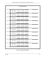
Page 47: ...ge Off Low High Heater Range Off Low High Heater Range Off Low High Heater Range Off Low High Heater Range Off Low High Heater Range Off Low High Heater Range Off Low High Heater Range Off Low High P 1 999 I 1 999 D 1 200 K K K K K K K K K K Zone Setting WorkSheet P 1 999 I 1 999 D 1 200 P 1 999 I 1 999 D 1 200 P 1 999 I 1 999 D 1 200 P 1 999 I 1 999 D 1 200 P 1 999 I 1 999 D 1 200 P 1 999 I 1 999...

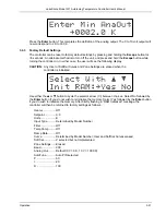
Page 48: ...g The default analog output has the 0 to 10 volts corresponding to 0 to 1000 K The resolution is 1 22 mV 0 122 K and the accuracy is 0 04 of full scale output measurement accuracy The user also has the option to rescale the analog output assigning new temperatures in kelvin to correspond to 0 and 10 V minimum temperature resolution is 0 1 K To program the analog output press the Analog Out button ...

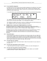
Page 49: ...tCal Curves and Zone Settings are erased when the controller is initialized Use either the s or t button to cycle the selector arrow between choices Select No followed by the Enter button if you do not wish to reinitialize the memory Select Yes followed by the Enter button if you do wish to initialize the memory After briefly flashing a RAM Initialized message the controller will then be returned ...

Page 50: ...to operate in temperature units C and K as well as voltage in millivolts The thermocouple input utilizes a secondary temperature sensor to monitor the Reference Junction room temperature and provide curve compensation Thermocouple Reference Junction Compensation can be disabled in order for the Model 321 to be used with external compensation techniques 3 5 1 Sensor Attachment Thermocouple leads ar...

Page 51: ...calibration If another thermocouple is attached or the thermocouple has aged or the configuration of the system is changed then the offset adjustment must be repeated 3 5 6 Curve Format The input is hardware limited to reading input between 45 mV and 45mV All curves should be limited in temperature so not to exceed these values If thermocouple compensation is desired the thermocouple curve must be...

Page 52: ...Lake Shore Model 321 Autotuning Temperature Controller User s Manual 3 24 Operation This Page Intentionally Left Blank ...

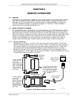
Page 53: ...ed to enable communication 4 1 1 Physical Connection The Model 321 has an RJ 11 connector on the rear panel for serial communication The original RS 232C standard specifies 25 pins but 9 pin 25 pin and RJ 11 connectors are commonly used in the computer industry For you convenience Lake Shore offers a Model 2001 RJ 11 Cable When combined with either the Model 2002 DB 25 Adapter or Model 2003 DE 9 A...

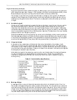
Page 54: ...or flow control and timing as described in Paragraph 4 1 5 4 1 3 Character Format A character is the smallest piece of information that can be transmitted by the interface Each character is 10 bits long and contains data bits bits for character timing and an error detection bit The instrument uses 7 bits for data in the ASCII format One start bit and one stop bit are necessary to synchronize conse...

Page 55: ...t takes 10 ms for the instrument to begin the response Some responses take longer 4 1 5 Message Flow Control It is important to remember that the user program is in charge of the serial communication at all times The instrument can not initiate communication determine which device should be transmitting at a given time or guarantee timing between messages All of this is the responsibility of the u...

Page 56: ...works with Visual Basic 6 0 VB6 on an IBM PC or compatible with a Pentium class processor A Pentium 90 or higher is recommended running Windows 95 or better with a serial interface It uses the COM1 communications port at 9600 Baud Use the following procedure to develop the Serial Interface Program in Visual Basic 1 Start VB6 2 Choose Standard EXE and select Open 3 Resize form window to desired siz...

Page 57: ...tatement Public gSend as Boolean b Double Click on cmdSend Add code segment under Private Sub cmdSend_Click as shown in Table 4 3 c In the Code Editor window under the Object dropdown list select Form Make sure the Procedure dropdown list is set at Load The Code window should have written the segment of code Private Sub Form_Load Add the code to this subroutine as shown in Table 4 3 d Double Click...

Page 58: ...r events Loop Until gSend True Loop until Send button pressed gSend False Set Flag as false strCommand frmSerial txtCommand Text Get Command strReturn Clear response display strCommand UCase strCommand Set all characters to upper case If strCommand EXIT Then Get out on EXIT End End If frmSerial MSComm1 Output strCommand Term Send command to instrument If InStr strCommand 0 Then Check to see if que...

Page 59: ... Basic Serial Interface Program CLS Clear screen PRINT SERIAL COMMUNICATION PROGRAM PRINT TIMEOUT 2000 Read timeout may need more BAUD 9600 TERM CHR 13 CHR 10 Terminators are CR LF OPEN COM1 BAUD O 7 1 RS FOR RANDOM AS 1 LEN 256 LOOP1 LINE INPUT ENTER COMMAND or EXIT CMD Get command from keyboard CMD UCASE CMD Change input to upper case IF CMD EXIT THEN CLOSE 1 END Get out on Exit CMD CMD TERM PRI...

Page 60: ...uery without a nothing will be returned Incorrectly spelled commands and queries are ignored Commands and queries and should have a space separating the command and associated parameters Leading zeros and zeros following a decimal point are not needed in a command string but they will be sent in response to a query A leading is not required but a leading is required 4 1 8 Trouble Shooting New Inst...

Page 61: ...y Filter Query 11 Control Process Commands Command Function Page TUNE Tune Status 12 TUNE Tune Query 12 SETP Set Setpoint 12 SETP Setpoint Query 12 GAIN Set Gain 13 GAIN Gain Query 13 RSET Set Reset 13 RSET Reset Query 13 RATE Set Rate 13 RATE Rate Query 13 RANG Set Range 14 RANG Range Query 14 HEAT Heater Query 14 ZONE Store Zone 14 ZONE Zone Query 14 RAMP Enable Disable Ramping 15 RAMP Ramping E...

Page 62: ...ned Manufacturer model number 0 firmware date Remarks Identifies the instrument model and software level 0 in the returned syntax is in place of the serial number Example LSCI MODEL321 0 121393 term CDAT Sensor Data Query Input CDAT Returned 000 0 Remarks A free field is active here The value returned is 7 characters a sign 5 digits and a decimal point The last digit may be a null Example 1 2345 t...

Page 63: ...ting The character returned will be K for kelvin C for Celsius V for volts R for Ohms or M for millivolts FILT Set Display Filter Input FILT 0 or FILT 1 Returned Nothing Remarks Used to turn the display filter on or off where 0 Off and 1 On Quiets the display by taking a running average of 10 readings FILT Display Filter Query Input FILT Returned 0 or 1 Remarks Returns the display filter setting w...

Page 64: ...hosen For Control Input SETP XXX X for temperature or SETP X XXXX for voltage Returned Nothing Remarks Fill in the setpoint parameter with a value from 0 through 999 9 for temperature or 0 through 2 499 for voltage Utilizes the free field format for the decimal point Example If in kelvin 1 SETP 77 2 term will result in the display showing 77 2 K 2 SETP 123 term will result in the display showing 1...

Page 65: ...SET Manual Mode Reset Setting Input RSET XXX Returned Nothing Remarks The reset parameter can be filled in with an integer from 0 through 999 Reset corresponds to the Integral I portion of the PID Autotuning control algorithm RSET Reset Query Input RSET Returned XXX Remarks Returns current reset setting The value returned is an integer from 000 through 999 Reset corresponds to the Integral I porti...

Page 66: ... XX SSS S R PPP III DDD Returned Nothing Remarks Stores the stated values of Setpoint Heater Range Gain Rate and Reset Zone XX is between 01 and 10 SSS S is the setpoint in kelvin R is the heater range PPP is the gain III is the Reset and DDD is the Rate The heater Range is 0 for Heater off 2 for Heater Low and 3 for Heater High Example ZONE 1 100 0 2 100 0 100 20 term instructs the Model 321 to s...

Page 67: ...ns a 0 if the ramping function is disabled or a 1 if the ramping function is enabled RAMPR Set Ramp Rate in Kelvin per Minute Input RAMPR XX X Returned Nothing Remarks XX X is the ramp rate in Kelvin per minute between 0 and 99 9 Example RAMP 10 term instructs the Model 321 to make the ramp rate equal to 10 K Min RAMPR Ramp Rate Query Input RAMPR Returned XX X Remarks Returns the current value of ...

Page 68: ... Returned XX Remarks Value returned is an integer from 00 through 12 corresponding to the currently selected sensor curve number Refer to Table 2 2 for a listing of sensor curve numbers ACOMP Set Room Temperature Compensation Model 321 04 Thermocouple Only Input ACOMP 0 or ACOMP 1 Returned Nothing Remarks Select temperature compensation parameter with 0 for off or 1 for on ACOMP Room Temperature C...

Page 69: ...The CURV11 command should be used to enter the first two points and then the ECUR11 command to add the remaining points one at a time up to a maximum of 97 points Remarks This command is used to establish and enter the first two points of the user curve in the following format S For the Model 330 the first character must be the letter S B Setpoint Limit where 0 325 K 1 375 K 2 475 K 3 800 K and 9 ...

Page 70: ... of the User Curve a QuickBASIC Curve Loading Program is provided in Paragraph 4 3 CURV Curve Number Information Query Input CURV XX Returned AA SB0CCCCCCCCCCCCCCC D XX Y YYYYY ZZZ Z Remarks User must provide curve number 00 thru 12 with query The instrument will return header line and all point information for that curve Information returned is defined as follows A Curve number The value will be ...

Page 71: ...added or edited where X XXXXX is voltage and YYY Y is the temperature in kelvin If the Model 321 does not recognize either the units value or the temperature value it will assume that you are entering a new point and place it in the proper ascending position Example If the point to be edited was input as 0 19083 364 0 and should have been 0 19083 365 0 input the command as follows ECUR 11 0 19083 ...

Page 72: ... 10 mV K 10 V analog output for 1000 K and 0 V for 0 K ANOH Set Analog Output Maximum High Input ANOH XXX X Returned Nothing Remarks Set the analog output maximum high where XXX X is between 0 and 999 9 Example ANOH 500 term instructs the Model 321 to make the 10 V output correspond to 500 K ANOH Analog Output Maximum High Query Input ANOH Returned XXX X Remarks Returns the current value of the te...

Page 73: ...riable lengths C SPACE 2000 Get the file name to load INPUT TYPE IN DRIVE NAME AND SERIAL NUMBER OF SENSOR AND PRESS ENTER A B A OPEN B FOR INPUT AS 1 Open ASCII disk file LINE INPUT 1 C Read disk file into string C STRIP MID C 9 Strip off the DRC series file header LOADER CURV11 STRIP Add the 300 series curve header PRINT LOADER Screen prints to show what is sent PRINT PRINT COMMANDS SENT TO 321 ...

Page 74: ...05 0 1 39908 1 00 0 1 40597 095 0 1 41258 090 0 1 41894 085 0 1 42509 080 0 1 43712 070 0 1 443 27 065 0 1 44993 060 0 1 45288 058 0 1 45611 056 0 1 45973 054 0 1 46394 052 0 1 46904 050 0 1 47551 048 0 1 48412 046 0 1 49606 044 0 1 51300 042 0 1 53706 040 0 1 55250 039 0 1 57064 038 0 1 59183 037 0 1 61638 036 0 1 64461 035 0 1 67679 034 0 1 71316 033 0 1 75390 032 0 1 79917 031 0 1 84902 030 0 1...

Page 75: ...bration being loaded on a floppy disk in ASCII format for Customer downloading 8001 Precision Option Factory Installed The Precision Option provides custom programming of specific sensor calibration curve at the factory The Precision Option improves combined sensor instrument accuracy to within 0 1 K or better over the calibrated temperature range of the sensor The Precision Option data is stored ...

Page 76: ...re Sensors 9001 00X Lake Shore Cryogenic Wire Lake Shore sells the following types of cryogenic wire DT Duo Twist MN Single Strand MW Manganin NC Nichrome Heater ND Heavy Duty QL Quad Lead and QT Quad Twist Please refer to the Lake Shore Accessories Catalog for details 9004 020 Apiezon N Grease 25 gram Tube General purpose grease well suited for cryogenic use because of its low viscosity It is oft...

Page 77: ...meters 14 feet C 321 5 1 eps Figure 5 1 Model 2001 RJ 11 Cable Assembly 43mm 1 69 inches 15 8mm 0 63 inches 25 1 55 mm 2 16 inches C 321 5 2 eps Figure 5 2 Model 2002 RJ 11 to DB 25 Adapter 60 3 mm 2 37 inches 15 9 mm 0 63 inches 9 1 32 5 mm 1 28 inches C 321 5 3 eps Figure 5 3 Model 2003 RJ 11 to DE 9 Adapter ...

Page 78: ...k Mount Handle 107 433 2 5 Screw 6 32 x 1 2 Inch 0 035 4 FHMS Phillips 6 Screw 8 32 x 3 8 Inch 0 081 6 FHMS Phillips Item Description P N Qty 1 2 3 4 6 5 5 6 6 4 Customer must use 5 64 2 mm hex key to remove four existing screws from sides of Model 321 NOTE Refer to Note Unit on right side mounting shown Unit on left side also possible C 321 5 4 eps Figure 5 4 Model 3022 Rack Mount Kit ...

Page 79: ... mm hex key to remove two 6 32 x 1 4 black button head screws from side of Instrument 2 Place Instrument on shelf 3 Use 5 64 inch 2 mm hex key to reinstall two 6 32 x 1 4 black button head screws through side of rack into corresponding holes in the side of the Instrument Installation Procedure Installation Procedure C 321 5 5 eps Figure 5 5 Model 3026 Dual Rack Mount Shelf ...

Page 80: ...Lake Shore Model 321 Autotuning Temperature Controller User s Manual 5 6 Accessories Probes This Page Intentionally Left Blank ...

Page 81: ...se rating is 0 75 A and the fuse type is 5 20 mm T Test fuse with ohmmeter Do not rely on visual inspection of fuse To clean the Model 321 periodically to remove dust grease and other contaminants perform the following 1 Clean front back panels and case with soft cloth dampened with mild detergent and water solution NOTE Do not use aromatic hydrocarbons or chlorinated solvents to clean the Model 3...

Page 82: ...LINE OFF OFF ON C 321 6 1 eps Figure 6 1 Power Fuse Access 6 3 REAR PANEL CONNECTOR DEFINITIONS The Serial I O Analog Output Sensor input and Heater Output connectors are defined in Figures 6 2 thru 6 5 6 5 4 3 2 1 SERIAL I O C 321 6 2 eps PIN DESCRIPTION 1 2 3 4 5 6 RS 232C In RxD RS 232C In RxD RS 232C Ground RS 232C Ground RS 232C Out TxD RS 232C Out TxD Figure 6 2 SERIAL I O RJ 11 Connector De...

Page 83: ...tor Ground Connector Shell Figure 6 3 ANALOG OUTPUT Connector Details SENSOR C 321 6 4 eps PIN DESCRIPTION 1 2 3 4 5 6 Current Voltage Current 500 µA Platinum Voltage Current 10 µA Diodes Shield Figure 6 4 Diode and Platinum SENSOR Connector Details HEATER OUTPUT HI LO GND C 321 6 5 eps PIN DESCRIPTION 1 2 3 HI LO GROUND Figure 6 5 HEATER Connector Details ...

Page 84: ...9 18 17 16 15 14 NOT USED 6 5 4 3 2 1 DB 25 CONNECTOR RJ 11 RECEPTACLE RxD Gnd TxD For Customer supplied computer with DB 25 Serial Interface Connector configured as DCE If the interface is DTE a Null Modem Adapter is required to exchange Transmit and Receive lines C 321 6 7 eps Figure 6 7 Model 2002 RJ 11 to DB 25 Adapter Wiring Details 5 4 3 2 1 9 8 7 6 NOT USED 6 5 4 3 2 1 DE 9 CONNECTOR RJ 11 ...

Page 85: ...nit 3 Use 5 64 hex key to loosen two screws attaching bottom panel to unit 4 Carefully remove back bezel 5 Slide top panel back and remove from unit 6 Locate software EPROM U22 Master or U19 Slave on main circuit board Note orientation of existing EPROMs circular notch on front of IC See Figure 6 10 7 Use IC puller to remove existing EPROM s from socket 8 Noting orientation of new EPROM s use IC i...

Page 86: ...isplayed 2 hold the Escape key down when the instrument is off and then turning the instrument on or 3 holding the Escape key down for more than 5 seconds Wait until a message is given before releasing the key The second error display is shown below This error message indicates that an attempt to write and then read the internal non volatile RAM was unsuccessful This error is not correctable by th...

Page 87: ... a 100 kΩ 0 01 25 ppm precision resistor available use the procedure in Paragraph 6 8 1 If no precision resistor is available use the optional procedure in Paragraph 6 8 2 6 8 1 Model 321 01 Calibration With Precision Resistor The Model 321 01 calibration with precision resistor is presented in four parts First is list of test equipment in Paragraph 6 8 1 1 Second is the test setup in Paragraph 6 ...

Page 88: ... from the 100 kΩ resistor 11 Configure the Model 321 to display units in voltage 12 Adjust R44 until the display reads exactly 1 0000 VDC 6 8 1 4 Analog Output Calibration Use the following procedure to perform the analog output calibration 1 Attach test leads to TP3 gnd1 and TP4 Analog out 2 Press and hold the Analog Out key until the Model 321 enters the Analog output calibration mode 3 Press th...

Page 89: ...Lake Shore Model 321 Autotuning Temperature Controller User s Manual Service 6 9 P 321 5 10 bmp Figure 6 10 Typical Model 321 PCB Layout ...

Page 90: ...t 2 Use 5 64 hex key to remove four screws attaching top panel to unit 3 Use 5 64 hex key to loosen two screws attaching bottom panel to unit 4 Carefully remove back bezel 5 Slide top panel back and remove from unit 6 8 2 3 Input Calibration Use the following procedure to perform the input calibration 1 Measure the resistance of the 100 kΩ resistor to the nearest 10 Ω and write it down 2 Place a s...

Page 91: ...ision resistor is available use the optional procedure in Paragraph 6 9 2 6 9 1 Model 321 02 Calibration With Precision Resistor The Model 321 02 calibration with precision resistor is presented in four parts First is list of test equipment in Paragraph 6 9 1 1 Second is the test setup in Paragraph 6 9 1 2 Third is the input calibration in Paragraph 6 9 1 3 Finally analog output calibration is pro...

Page 92: ...rt from the 100 Ω resistor 11 Configure the Model 321 to display units in ohms 12 Adjust R42 until the display reads exactly 100 00 Ω 6 9 1 4 Analog Output Calibration Use the following procedure to perform the analog output calibration 1 Attach test leads to TP3 gnd1 and TP4 Analog out 2 Press and hold the Analog Out key until the Model 321 enters the Analog output calibration mode 3 Press the Up...

Page 93: ...form this procedure 1 Set power switch to off and disconnect power cord from rear of unit 2 Use 5 64 hex key to remove four screws attaching top panel to unit 3 Use 5 64 hex key to loosen two screws attaching bottom panel to unit 4 Carefully remove back bezel 5 Slide top panel back and remove from unit 6 9 2 3 Input Calibration Use the following procedure to perform the input calibration 1 Measure...

Page 94: ...libration With Millivolt Voltage Standard The Model 321 04 calibration with Millivolt Voltage Standard is presented in six parts First is list of test equipment in Paragraph 6 10 1 1 Second is the test setup in Paragraph 6 10 1 2 Third is the input calibration in Paragraph 6 10 1 3 Fourth is the analog output calibration is provided in Paragraph 6 10 1 4 Fifth is the thermocouple offset adjustment...

Page 95: ... Up arrow key until Zero is selected 4 With the DMM in DC voltage mode adjust R22 until the voltage is 0 000 0 001 VDC 5 Press the Up arrow key until Span is selected 6 Adjust R18 until the voltage is 10 000 0 001 VDC 7 Press Escape on the Model 321 to exit the Analog output calibration mode 8 Set power switch to off O Disconnect power cord and test resistor 9 Replace top of enclosure and secure w...

Page 96: ... in Paragraph 6 10 2 1 Second is the test setup in Paragraph 6 10 2 2 Third is the input calibration in Paragraph 6 10 2 3 Fourth is the analog output calibration is provided in Paragraph 6 10 2 4 Fifth is the thermocouple offset adjustment in Paragraph 6 10 2 5 Finally the internal thermocouple compensation calibration is provided in Paragraph 6 10 2 6 These procedures will be performed with powe...

Page 97: ... display exactly matches the DMM reading 13 Reverse voltage source to 44 0 mV DC The Model 321 display should match the DMM reading within 0 002 mV DC If not set voltage source to zero volts and repeat steps 8 through 13 6 10 2 4 Analog Output Calibration Use the following procedure to perform the analog output calibration 1 Attach test leads to TP3 GND1 and TP4 Analog out 2 Press and hold the Ana...

Page 98: ... the desired temperature units 4 Turn off thermocouple compensation 5 Adjust R27 until the display reads the reference temperature 6 Close the Model 321 enclosure Refer to Paragraph 6 10 1 4 Steps 8 10 6 10 2 6 Internal Thermocouple Compensation Calibration When a new or different thermocouple is attached to the instrument and internal thermocouple compensation is being used it may be necessary to...

Page 99: ...7 7 0 1443 3 665 17 0 0453 1 150 27 0 0142 0 3606 37 0 00445 0 1131 8 0 1285 3 264 18 0 0403 1 024 28 0 0126 0 3211 38 0 00397 0 1007 9 0 1144 2 906 19 0 0359 0 9116 29 0 0113 0 2859 39 0 00353 0 08969 10 0 1019 2 588 20 0 0338 0 8118 30 0 0100 0 2546 40 0 00314 0 07987 ambient temperature The temperature of the surrounding medium such as gas or liquid which comes into contact with the apparatus 1...

Page 100: ...ormal atmospheric pressure Celsius degrees are purely derived units calculated from the Kelvin Thermodynamic Scale Formerly known as centigrade See Temperature for conversions Cernox A Lake Shore resistance temperature detector based on a ceramic oxy nitride resistance material CGR Carbon Glass Resistor cgs system of units A system in which the basic units are the centimeter gram and second 2 Chro...

Page 101: ...e data and Windows resources that multiple Windows programs can access electromagnet A device in which a magnetic field is generated as the result of electrical current passing through a helical conducting coil It can be configured as an iron free solenoid in which the field is produced along the axis of the coil or an iron cored structure in which the field is produced in an air gap between pole ...

Page 102: ...gth range 770 to 106 nanometers is considered infrared energy 2 The full range is usually divided into three sub ranges near IR far IR and sub millimeter input card Electronics on a printed circuit board card that plug into an instrument main frame Used by configurable instruments to allow for different sensor types or interface options interchangeability Ability to exchange one sensor or device w...

Page 103: ...tic field strength H depends upon the past history of the samples magnetization magnetic induction B See magnetic flux density magnetic moment m This is the fundamental magnetic property measured with dc magnetic measurements systems such as a vibrating sample magnetometer extraction magnetometer SQUID magnetometer etc The exact technical definition relates to the torque exerted on a magnetized sa...

Page 104: ... kPa Variations include psi absolute psia measured relative to vacuum zero pressure where one atmosphere pressure equals 14 696 psia and psi gauge psig where gauge measured relative to atmospheric or some other reference pressure ppm Parts per million e g 4 10 6 is four parts per million precision Careful measurement under controlled conditions which can be repeated with similar results See repeat...

Page 105: ... Also known as effective value 1 room temperature compensation Thermocouples are a differential measurement device Their signal represents the difference in temperature between their ends An ice bath is often used to reference the measurement end to 0 degrees Celsius so most curves are normalized to that temperature Room temperature compensation replaces an ice bath by monitoring the temperature o...

Page 106: ...the Seebeck effect 1 thermocouple A pair of dissimilar conductors so joined at two points that an electromotive force is developed by the thermoelectric effects when the junctions are at different temperatures 2 thixotropy Property of certain gels which liquefy when subjected to vibratory forces such as ultrasonic waves or even simple shaking and then solidify again when left standing 1 tolerance ...

Page 107: ... properly cooled A quick comparison between LHe and LN2 is provided in Table B 1 Table B 1 Comparison of Liquid Helium to Liquid Nitrogen PROPERTY LIQUID HELIUM LIQUID NITROGEN Boiling Point 1 atm in K Thermal Conductivity Gas w cm K Latent Heat of Vaporization Btu liter Liquid Density pounds liter 4 2 0 083 2 4 0 275 77 0 013 152 0 78 B3 0 HANDLING CRYOGENIC STORAGE DEWARS All cryogenic container...

Page 108: ...or the cold gas issuing from it Protect your eyes with full face shield or chemical splash goggles Safety glasses even with side shields are not adequate Always wear special cryogenic gloves Tempshield Cryo Gloves or equivalent when handling anything that is or may have been in contact with the liquid or cold gas or with cold pipes or equipment Long sleeve shirts and cuffless trousers that are of ...

Page 109: ... 0 0 73440 230 0 0 68580 046 0 0 07909 9 170 0 0 73582 130 0 0 84490 195 0 0 76717 052 0 0 09924 10 130 0 0 84606 100 0 0 92570 165 0 0 83541 058 0 0 12180 11 090 0 0 95327 075 0 0 99110 140 0 0 89082 065 0 0 15015 12 070 0 1 00460 060 0 1 02840 115 0 0 94455 075 0 0 19223 13 055 0 1 04070 040 0 1 07460 095 0 0 98574 085 0 0 23525 14 040 0 1 07460 036 0 1 08480 077 4 1 02044 105 0 0 32081 15 034 0...

Page 110: ... 5 2982 2 8 0 4 6067 3 0 5 2815 3 13 5 4 5259 4 8 5 2594 4 18 0 4 4571 7 0 5 2285 5 24 0 4 3703 10 5 5 1742 6 30 0 4 2869 19 0 5 0315 7 52 0 3 9928 26 0 4 9126 8 60 0 3 8830 48 0 4 5494 9 65 0 3 8126 58 0 4 3810 10 70 0 3 7411 70 0 4 1733 11 80 0 3 5948 80 0 3 9952 12 90 0 3 4436 90 0 3 8132 13 105 0 3 2026 100 0 3 6270 14 115 0 3 0374 110 0 3 4370 15 125 0 2 8689 120 0 3 2435 16 135 0 2 6957 135 ...

Page 111: ... 9 7570 19 5 6 4205 22 0 6 1888 6 25 0 9 7013 25 0 6 3951 29 0 6 1404 7 32 0 9 6204 32 0 6 3529 38 0 6 0615 8 40 0 9 5071 40 0 6 2913 48 0 5 9535 9 50 0 9 3366 48 0 6 2149 60 0 5 7995 10 60 0 9 1345 58 0 6 1022 75 0 5 5753 11 70 0 8 9030 65 0 6 0099 90 0 5 3204 12 80 0 8 6475 75 0 5 8634 105 0 5 0337 13 90 0 8 3673 85 0 5 6989 120 0 4 7194 14 105 0 7 9064 95 0 5 5156 135 0 4 3767 15 120 0 7 3943 1...

Page 112: ...Lake Shore Model 321 Autotuning Temperature Controller User s Manual C 4 Curve Tables This Page Intentionally Left Blank ...

Page 113: ...ing inside a furnace for example 1 The values of heat capacity lower Cp and thermal conductivity often higher κ are such that much shorter thermal time constants τ α Cp κ are the rule at low temperatures 2 The temperature sensor used in a furnace is almost always one of a variety of thermocouples with sensitivities in the 10 100uV C range In the cryogenic regime resistance thermometers both metall...

Page 114: ...s in an audio amplifier but is related to the maximum amount of error signal allowed before the controller is directed to produce full output power The DRC 82C requires a 0 to 8 volt signal from the deviation amplifier to drive the power output stage from zero to maximum In Figure 2 For Av 1000 there is a narrow band of error signals 0 to 8 mV within which the proportional action occurs This propo...

Page 115: ...the system and assume that to control at 20 kelvin the heating power required is 0 2 watts Assume also that 50 watts of heater power is available reducible in five steps of one decade each Figure 5 shows the control offset for an amplifier gain of 100 and three output power settings which will deliver enough power to the system to balance the cooling power The temperature offsets for a power level...

Page 116: ...n reset control IV PROPORTIONAL GAIN PLUS INTEGRAL RESET TEMPERATURE CONTROL The manual reset adjustment described above varies markedly with the temperature set point and with the often changing heater power demands of the system Thus it is normally neither convenient nor desirable to have to resort to such a means of eliminating temperature droop offset Instead suppose a circuit could be added t...

Page 117: ...stems this time lag can be 10 30 minutes In cryogenic systems it is usually less than a minute even near room temperature Consequently placement of the control sensor with respect to the heater is extremely important in the design of a cryogenic system as is the placement of both the heater and sensor with respect to the cooling power Rate action can be achieved by means of a differentiator circui...

Page 118: ... such resolution have sampling times in the half second range In the world of ovens furnaces and other large industrial processes which operate above room temperature stable control can be maintained by digital systems updating temperature only once or twice a second This is for the same reason that ON OFF controllers are successful in these cases the large thermal time constants of the controlled...

Page 119: ...l December 1984 pp 132 136 Some of this material has appeared in Principles of Temperature Control available from Gulton Industries West Division Unlike reference 1 the discussion is not related to cryogenics but temperature control system principles are briefly and clearly explained 3 C L Pomernacki Micro Computer Based Controller for Temperature Programming the Direct Inlet Probe of a High Resol...

Page 120: ... 1 17705 1 15558 1 13598 1 12463 1 11896 1 11517 1 11212 1 10945 1 10702 1 10263 1 09864 1 09490 1 09131 1 08781 1 08436 1 08093 1 07748 1 07402 1 07053 1 06700 1 06346 1 05988 1 05629 1 05267 1 04353 1 03425 1 02482 1 01525 1 00552 0 99565 18 6 18 2 18 0 17 7 17 6 17 4 17 4 17 4 17 6 18 5 20 6 21 7 15 9 7 72 4 34 3 34 2 82 2 53 2 34 2 08 1 92 1 83 1 77 1 74 1 72 1 72 1 73 1 74 1 75 1 77 1 78 1 79...

Page 121: ...nteresting property of the Chebychev fits is evident in the form of the Chebychev polynomial given in Equation 4 No term in Equation 1 will be greater than the absolute value of the coefficient This property makes it easy to determine the contribution of each term to the temperature calculation and where to truncate the series if full accuracy is not required Program 1 BASIC Subroutine to evaluate...

Page 122: ...room temperature and cryogenic temperatures to guarantee that heat is not being conducted through the leads to the sensor A final thermal anchor at the sample itself is a good practice to assure thermal equilibrium between the sample and temperature sensor Note that the CU CY BO and DI mounting adapters serve as their own sample thermal anchor If the connecting leads have only a thin insulation su...

Page 123: ...der Clean both the sensor and mounting surface of any residual flux Next re heat the mounting surface to the melting point of the solder press the device into position and allow the sensor to warm to the melting point of the solder After both tinned surfaces have flowed together remove the heat source and let the sample and sensor cool Under no circumstance should the sensor be heated above 200 C ...

Page 124: ...y DT 470 CO The CO adapter is a spring loaded clamp to attach the DT 470 SD package to a flat surface It maintains pressure on the SD package as the temperature varies First remove the hold down cap which holds the three piece CO assembly together The CO assembly should appear as shown in the accompanying drawings Bolt the assembly into a 4 40 threaded hole The stop on the brass screw should rest ...

Page 125: ...ltiplying the above sensitivity by the desired temperature resolution in kelvin will give the required voltage resolution in millivolts The static impedance of the DT 470 sensor operating at a 10 microampere current is on the order of 100 000ohms Therefore the input impedance of the voltmeter must be significantly larger than this to avoid measurement errors Voltmeters with input impedances of gre...

Page 126: ... reproducibilities to better than 50 mK Figure 1 shows the voltage variation with temperature for a typical silicon diode temperature sensor An error arises in diode thermometry if the excitation current is not a true dc current but has an ac component superimposed on the dc Although the ac component can be due to a poorly designed current supply a more common source of the ac is noise induced in ...

Page 127: ...50 µA Although detailed measurements were taken on only one diode other diodes were randomly selected and spot checked at all three temperatures and frequencies to verify consistency with the measured data The diodes tested were of the DT 500 series of Lake Shore Cryotronics Inc and have been in production long enough to have a substantial reliability and calibration history III RESULTS AND DISCUS...

Page 128: ...re T the period of integration of the voltmeter or approximately 2π ω Implied in this derivation is the assumption that ω is sufficiently small so that effects from diode capacitance on the order of picofarads can be ignored On carrying out the integration of Eq 3 and subtracting V Idc the dc offset voltage is V V V I nkT e eV nkT dc rms F HG I KJ F H GG I K JJ L N MM O Q PP ln 1 2 1 1 2 2 4 where...

Page 129: ...difference The details of the extended calculation have not been given as the mathematics is somewhat tedious and the slight discrepancies between the small signal model and the extended model do not justify the added complexity For all practical purposes Eq 6 can be reliably used above 40 K The physics of a p n junction at 4 2 K is not clearly understood and attempts to correlate the present data...

Page 130: ...housand ohms at a 10 µA operating current A capacitor in the range of 10 to 20 µF should reduce most noise effects to an acceptable level However because the capacitor increases the time constant in the circuit a sluggish response should be expected In switching operations 30 seconds or more may be required for the circuit to stabilize This quick fix is not meant as a substitute for proper measure...

Reviews: