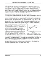
Lake Shore Model 321 Autotuning Temperature Controller User’s Manual
Application Notes
D-11
DT-470-SD
The SD version is the basic package for the DT-470 sensor line from which all
other configurations are made using the appropriate adapter. The base of the
device has a gold metallized surface and is the largest flat surface on the sensor.
The base is electrically isolated from the sensing element and leads, and all
thermal contact to the sensor must be made through the base. A thin braze joint
around the sides of the SD package is electrically connected to the sensing
element. Contact to the sides with any electrically conductive material must be
avoided. When viewed with the base down and with leads towards the observer,
the positive lead (anode) is on the right.
For a removable mount, the Sd sensor can be3 held against the mounting surface with the CO adapter (see below) or
similar clamping mechanism. Any method of clamping the sensor must avoid excessive pressure and should be designed
so that thermal contractions or expansions do not loosen contact with the sensor. For uses restricted to below 325 K, a
thin layer of Apiezon N Grease should be used between the sensor and sample to enhance the thermal contact.
The SD package can also be bonded with an epoxy such as Stycast. The sensor should be pressed firmly against the
surface during curing to assure a thin epoxy layer and good thermal contact. The device may be removed in the future by
using the appropriate epoxy stripper.
The SD adpater can be soldered using a rosin flux (non-corrosive) if extreme care is exercised. First, tin the base of the
sensor using a low wattage, temperature controlled soldering iron which will not exceed 200° C. Use only a minimal
amount of solder. Tin the surface to which the sensor is to bonded and again avoid an excessive thickness of solder.
Clean both the sensor and mounting surface of any residual flux. Next, re-heat the mounting surface to the melting point
of the solder, press the device into position and allow the sensor to warm to the melting point of the solder. After both
tinned surfaces have flowed together, remove the heat source and let the sample and sensor cool. Under no
circumstance should the sensor be heated above 200° C and the solder must be limited to only the base of the sensor.
Excess solder running up the sides of the SD package can create shorts. Repeated mounting and demounting of a
soldered sensor may eventually cause wetting deterioration and ruin the thermal contact to the sensing element, although
the nickel buffer layer should minimize these problems.
CAUTION: The preferred method for mounting the SD sensor is either the CO adapter or bonding with epoxy.
Lake Shore Cryotronics, Inc. will not warranty replace any device damaged by a user-designed clamp or
damaged through solder mounting.
DT-470-LR
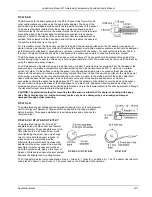
The gold-plated copper LR adapter is designed for insertion into a 1/8 inch diameter
hole. A thin layer of Apiezon N Grease should be applied to the copper adapter
before insertion. This eases installation at room temperature and enhances the
thermal contact.
DT-470-CU / DT-470-DI / DT-470-CY
The gold-plated copper CU, DI, and CY
adapters serve as both sensor and thermal
anchor assembly. These adapters mount to a
flat surface with a 4-40 brass screw. Avoid
over-tightening the screw; use only enough
force to firmly hold the sensor in place. A
brass screw is recommended as the
differential thermal contraction between the
adapter and the screw causes the mounting
assembly to tighten as opposed to loosen
when the system cools. Apply a thin layer of
Apiezon N Grease to enhance thermal contact
between the adapter and mounting surface.
The CU adapter has four color-coded leads: Red (I-), Green (V-), Clear (V+), and Blue )I+). The CY adapter has two color-
coded leads: Yellow (+) and Green (-). The green lead on the DI adapter is the cathode.
DT-470-CU / DT-470-DI
DT-470-CY


