background image

http://www.lairdconnect.com 

16 

© Copyright 2020 Laird Connectivity, Inc..  

All Rights Reserved 

Americas

: +1-800-492-2320 

Europe

: +44-1628-858-940 

Hong Kong

: +852 2923 0610 


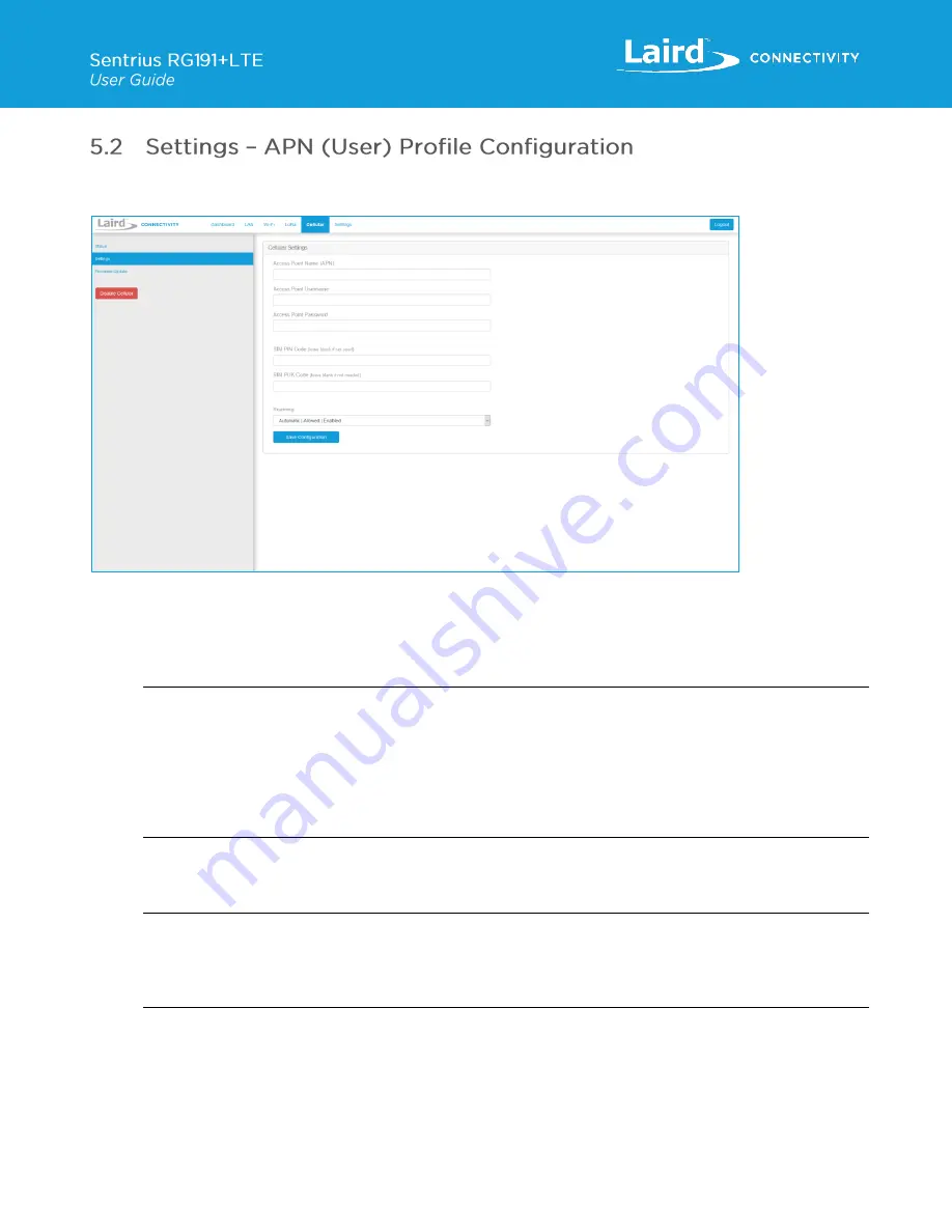
Select the Modem Configuration page by clicking the 

Settings

 menu item in the side menu of the Cellular view (

Error! 

Reference source not found.

). 


Figure 16: Cellular Settings page 

1.  Depending on your service provider that issued the SIM card you may have to add extra information about your 

Access Point Name

 (APN), Access Point Username and Access Point Password for authentication purposes. If you 

are unsure about these settings, please contact your mobile service provider and/or SIM card provider. However, 
most providers do not require this information to be entered. 

Note

: The RG191+LTE gateway comes with a preinstalled Truphone SIM card: Navigate to 

https://iot.truphone.com


to register and activate your SIM card. Select a data plan that meets your data needs for your application. 
This is a subscription plan. 


Enter Truphone’s APN: 

iot.truphone.com

 in the APN field and save the configuration to start the cellular 

service. This requires a reboot.  

** Cellular must be enabled in order to utilize the cellular feature.


2.  If your SIM card is protected, you should add your 

PIN

 and/or 

PUK

 code where needed (

otherwise leave these 

fields empty

). Reference the SIM card and/or mobile service provider documentation for more details on the 

necessary settings to configure. 

Note

: The RG191+LTE gateway comes with a preinstalled Truphone SIM card which, once registered and activated 

following the link above, does 

NOT

 require a PIN and/or PUK code by default.  

If using the preinstalled Truphone SIM card, leave these fields blank.  

** Cellular must be enabled in order to utilize the cellular feature.


3.  Choose a 

Roaming option

. By default, roaming is enabled, and in most cases, it is recommended. For Roaming 

there are two options available 

– 

Allowed

 and 

Disallowed

. When roaming is Disallowed, your network preference is 

restricted to home-only; no resources from other operator's network will be used in that case. 

4.  Apply your settings by clicking on the 

Save Configuration

 button and 

reboot

 the gateway when requested. 


Summary of Contents for Sentrius RG191+LTE

Page 1: ...Version 2 0 ...

Page 2: ...ll release Modifications to regulatory certification statements Robert Gosewehr Chris Boorman 1 1 14 Oct 2020 Updated Error Reference source not found to 22cm separation distance Erik Lins Jonathan Kaye 1 2 6 Nov 2020 Added PTCRB Certification Dave Drogowski Jonathan Kaye 1 3 11 Nov 2020 Added note to Section 5 2 Adam Ruehl Chris Boorman 1 4 4 Jan 2021 Addition of section 5 3 Adam Ruehl Chris Boor...

Page 3: ...can to Add a Profile 20 7 2 Manually Adding a Profile 21 7 3 Wi Fi Advanced Page 22 8 LoRa Connection Setup 22 8 1 Using Presets 23 8 2 Semtech Basic Station 24 8 3 Senet 26 8 4 Semtech Legacy UDP Forwarder 26 8 5 Advanced Configuration 29 8 6 Traffic 30 9 Manage the Gateway 31 9 1 Changing Username and Password 31 9 2 Web Session 31 9 3 Version Information 32 9 4 Updating Firmware 33 9 5 Save Res...

Page 4: ...d proven and reliable 50 Series Wireless Bridge certified module it also offers enterprise dual band Wi Fi and wired Ethernet for complete design freedom Based on the Semtech SX1301 SX1257 chipset designs it offers a LoRa range up to ten miles and pre loaded LoRa Packet Forwarder software options perfect for highly scalable flexible IoT networks The Sentrius RG191 LTE Gateway works with Laird s Se...

Page 5: ... 20 MHz wide channels 802 11a UNII 1 UNII 2A UNII 2C or CH 36 CH140 6 Mbps 17 dBm 54 Mbps 14 dBm 802 11a UNII 3 or CH 148 CH 165 6 Mbps 15 dBm 54 Mbps 14 dBm 802 11b 1 Mbps 17 dBm 11 Mbps 17 dBm 802 11g 6 Mbps 17 dBm 54 Mbps 14 dBm 802 11n 2 4 GHz 6 5 Mbps MCS0 17 dBm 65 Mbps MCS7 13 dBm 802 11n 5 GHz UNII 1 UNII 2A UNII 2C or CH 36 CH140 6 5 Mbps MCS0 HT20 17 dBm 65 Mbps MCS7 HT20 13 dBm MCS0 HT4...

Page 6: ...ltage 12V 1A Power Adapter External DC Power Supply has 12V 2A rating with regional plug adapter Security Wi Fi Standards WEP WPA WPA2 Encryption WEP TKIP AES EAP Types EAP FAST EAP TLS EAP TTLS PEAP GTC PEAP MSCHAP PEAP MSCHAPv2 PEAP TLS LEAP Software Operating System Embedded Linux 4 x Kernel LoRa Packet Network Forwarder with default support for the following The Things Network with Semtech Bas...

Page 7: ...LTE Antenna Model Laird Blade DBA6927C FSMAM Type Dipole Connector RP SMA Antenna Gain Up to 2 2dBi Accessories Included 1 x 902 928 MHz antenna 1 x LTE antenna 2 x 2 4 5 GHz Wi Fi antennas 1 x External DC power adapter Enclosure Standard Moulded plastic housing Warranty One year warranty Table 1 Ordering information Part Number Description 450 00107 K1 Kit Sentrius RG191 Gateway LTE CAT 1 NA 450 ...

Page 8: ...his follow these steps 1 Follow the label on the box and connect the four antennas Refer to Antenna Configuration for additional information 2 Connect the power supply see 2 in Figure 3 3 Connect the gateway to your router 3 in Figure 3 using the Ethernet cable 1 in Figure 3 Alternatively use the Wi Fi Quick Config mechanism Refer to Wi Fi Quick Configuration for additional information Your gatewa...

Page 9: ... follow these steps 1 Unscrew the four 4 back Torx screws using a T8 Torx screwdriver for the non IP67 gateway version Unscrew the thirteen 13 screws using a Philips screwdriver for the IP67 gateway version Figure 4 Gateway Screw Locations Left Standard Right IP67 2 Carefully move the top enclosure lid to the back of the gateway for the indoor non IP67 version as seen below Remove the top lid for ...

Page 10: ...ondary set of punch out lines from the center moving outward Figure 6 SIM Card Punch Out 4 Install the SIM card into the SIM card slot in the upper right location near the LTE modem making sure the copper contact side of the SIM card is facing down follow Blue Arrow Re close the gateway and screw down the screws when complete Figure 7 SIM Install Right Picture of SIM card contact side Note To remo...

Page 11: ... Updating Gateway Firmware for additional information regarding this upgrade The gateway includes a mode to allow you to configure without ethernet access in the case that you wish to join a wireless network Apply power to the gateway and allow to start then perform the following 1 Depress and hold the user button see 2 in Figure 2 for seven seconds 2 From a wirelessly enabled device perform a sca...

Page 12: ...ast three bytes are highlighted Figure 8 Figure 8 Bottom label last three bytes of the Ethernet MAC address highlighted 2 Enter the URL into the web browser to access the web interface For example for the gateway used in this guide the URL is https rg1xx29378B local where 29378B are the last six digits of the Ethernet MAC address In Wi Fi quick config mode the gateway can also be accessed via the ...

Page 13: ...852 2923 0610 5 Click Proceed Figure 10 Figure 10 Web interface second screen 6 Log on using the following default credentials Username sentrius Password RG1xx Figure 11 Gateway interface login screen After logging in the program warns you to change the default credentials for security reasons Figure 12 Figure 12 Change the default credentials ...

Page 14: ...ature only works with the RG191 LTE hardware see Ordering Information for product part numbers The Cellular menu supports modem configuration and firmware updates The current status of the integrated Cellular modem is also displayed To access this section click the Cellular tab from the ribbon at the top of the page In the sidebar on the left Error Reference source not found you can navigate vario...

Page 15: ...CID number of the attached U SIM card only if not locked SIM Card Status Shows the current state of the SIM card and whether a password PIN PUK is required Registration Roaming State Shows information about the network registration and roaming state Provider Shows information about the current service provider which the Cellular modem is attached to Network Technology Shows information about the c...

Page 16: ...Truphone s APN iot truphone com in the APN field and save the configuration to start the cellular service This requires a reboot Cellular must be enabled in order to utilize the cellular feature 2 If your SIM card is protected you should add your PIN and or PUK code where needed otherwise leave these fields empty Reference the SIM card and or mobile service provider documentation for more details ...

Page 17: ...ded In most cases this is not required However not all service provider hand out DNS Server s by default Also there are situations where you may want to overwrite the existing configuration For example if the DNS Server s do not perform well or when it is required by your application Apply your settings by clicking on the Save Advanced Settings button and reboot the gateway when requested Note If ...

Page 18: ...tings except IP Address Acquisition Method are greyed out IP values provided by DHCP are displayed but cannot be changed Static When the IP Address Acquisition Method is set to static all IP settings are fixed and saved in the device The external Gateway IP address is optional and may be left blank DNS Server IP addresses are also optional Zero one or two DNS servers may be specified Select the IP...

Page 19: ...ay apply to the current mode of operation This view is intended to support advanced users in troubleshooting their network Figure 19 Advanced view By default the gateway s Wi Fi radio is not configured to connect to a Wi Fi network The user must access the web interface on the gateway via the Ethernet interface to setup the Wi Fi connection To setup a Wi Fi connection click the Wi Fi tab in the ma...

Page 20: ...rofile follow these steps Connect to a Wi Fi network click Scan to scan for nearby Wi Fi networks Scanning continues until you click Stop or click on one of the listed scan results Figure 21 Figure 21 Scan function Click on the applicable scan result In the Wi Fi profile window enter the appropriate credential information for your chosen Wi Fi network Figure 22 Figure 22 Wi Fi profile window ...

Page 21: ...n click the Profiles button in the left menu This page is useful for adding a hidden Wi Fi network that is not broadcasting its SSID Figure 23 Figure 23 Wi Fi profiles page The profile page shows all Wi Fi profiles that are saved in the gateway You can add activate or delete the profiles shown on this page Click Profile to display the Wi Fi profile dialog Figure 24 Figure 24 Wi Fi profile dialog E...

Page 22: ...nd allows the user to configure the Quick Config AP mode password Figure 25 Figure 25 Wi Fi Advanced page The side panel for the LoRa Gateway allows selections for configuration and status of the LoRa network card The status of the LoRa Network is also displayed Figure 26 Figure 26 LoRa connection setup page Note The LoRa Region Code is displayed here Be sure that the gateway you are operating mat...

Page 23: ... third party server or as the basis for a private network These presets configure the forwarder and the channel plan To apply a preset configuration follow these steps Click the LoRa tab in the main menu The default page of the LoRa menu is the Presets page also accessible in the left side menu of the LoRa pages Select the preset from the drop down Information about this preset is displayed in a p...

Page 24: ...in a valid LNS server to allow for operation as a packet forwarder The CUPS servers are optional but should be kept blank if you do not want to communicate with the CUPS servers to provision the LNS certificates Figure 29 LNS server Each of the three servers has a set of certificates used to authenticate the server to the gateway and the other way around It is possible to function in a mode where ...

Page 25: ...44 1628 858 940 Hong Kong 852 2923 0610 Figure 30 Certificate selection The status of the connection to the LNS is shown on the sidebar when in the LoRa view Figure 31 LoRa view In the Dashboard view the status is shown with a circle that will be green when connected and black when disconnected Figure 32 Dashboard view ...

Page 26: ...ttings The forwarder page allows configuration of the packet forwarder The mode allows the user to change to different packet forwarders The configuration changes based on what packet forwarder is used Figure 33 Semtech packet forwarder configuration The radio page provides configuration of the radios and channels The LoRa card has two radios Radio 0 and Radio 1 This interface allows advanced user...

Page 27: ...annel s frequency is an offset of its radio s center frequency For most channels with a 125 kHz bandwidth the offset can be 0 4 to 0 4 MHz LoRa STD and FSK channels have configurable bandwidth For these channels when operating in 250 kHz or 500 kHz bandwidth the offset can be 0 3 to 0 3 MHz Each channel should be placed at least 200 kHz from any other channel otherwise the channel s bandwidth over...

Page 28: ... 44 1628 858 940 Hong Kong 852 2923 0610 Figure 37 Overlapping channels Gateways that operate in the US region should have a 500 kHz channel In Figure 38 the allowed placement of these channels displays larger and blue If a 500 kHz channel is not configured the interface displays a warning Figure 38 US region gateways ...

Page 29: ...The current configuration may be saved as a JSON text file This file can also be uploaded to restore the saved configuration This feature is useful for configuring multiple gateways with the same configuration Figure 40 Note If the forwarder settings contain credentials these are not saved in the configuration file for security reasons The user must take care to set the appropriate credentials whe...

Page 30: ...ge is only available when using certain forwarders When navigating to the traffic page any recent traffic that has been seen by the gateway displays To watch live traffic click Poll Traffic Traffic columns can be sorted and filters can be applied to one column at a time Figure 41 LoRa traffic Clicking on a traffic row displays packet details Figure 42 LoRa packet details ...

Page 31: ...rd Click Update Figure 43 Change username and password The user can change the web session timeout The web session timeout is the amount of time before the user will be warned and automatically logged out if there is no web activity Activity is defined as navigating between pages changing any settings or polling LoRa traffic The minimum time and default is five 5 minutes and the maximum time is 60...

Page 32: ...of various components in the gateway The Build string is the overall firmware version for the gateway software package If a firmware update is available New Build Available row displays Figure 45 Version information The Cellular Status page shows detailed software firmware information of the cellular modem in the gateway The Firmware Revision string is the firmware version for the modem software p...

Page 33: ... settings the user does not wish to lose beforehand 1 Click the tab in the main menu Then click Update Firmware in the left menu 2 Use a valid Firmware Update URL provide by Laird Connectivity once an update is available it will be defined within this user guide 3 Start the Firmware Update by clicking on button Start Update This may take a while The firmware update process downloads the firmware t...

Page 34: ...0 Hong Kong 852 2923 0610 4 At the end of the update you are prompted to reboot the gateway Click Reboot The gateway must be rebooted for the update to take effect Figure 49 Figure 49 Reboot prompt This is the initial production release firmware https connectivity firmware s3 amazonaws com rg1xx lora gateway firmware 93 9 5 7 fw txt ...

Page 35: ...ar modem to the newest available version Note Modem firmware updates should only be performed when something is not working you are facing connection problems or you have been instructed to do so by the Laird Connectivity support team 1 Before starting please make sure that the Cellular Modem is turned on and you have restarted the Gateway 2 Use a valid Firmware HTTP S DFOTA Delta Firmware Upgrade...

Page 36: ...managed remotely via TR 069 It requires an externally hosted Auto Configuration Server ACS to use this feature This allows a system administrator to access the gateways without needing physical access to the gateway or access behind a firewall The gateway will periodically initiate connections with the ACS allowing a user to remotely update LoRa configuration settings update firmware download logs...

Page 37: ...igured gateway then upload that generated configuration file to be pushed to all the units once the system administrator is satisfied that all the settings are correct on the golden unit A download is initiated by the ACS with the type 3 Vendor Configuration File and an upload is also initiated by the ACS with the type 3 Vendor Configuration File The ACS will not put a file extension on the downlo...

Page 38: ...Laird ActiveProfileSettings Parameter Name R W Description Input Data InternetGatewayDevice Laird ActiveProfileSettings O Active Wi Fi profile node N A InternetGatewayDevice Laird ActiveProfileSettings ProfileName R W Wi Fi profile name not SSID String representing the profile name InternetGatewayDevice Laird ActiveProfileSettings SSID R W Wi Fi network SSID String representing the SSID InternetGa...

Page 39: ...Settings IgnoreNullSSID R Hardcoded Wi Fi settings in the gateway N A InternetGatewayDevice Laird WIFIGlobalSettings PMKCaching R Hardcoded Wi Fi settings in the gateway N A InternetGatewayDevice Laird WIFIGlobalSettings ProbeDelay R Hardcoded Wi Fi settings in the gateway N A InternetGatewayDevice Laird WIFIGlobalSettings RegulatoryDomain R Hardcoded Wi Fi settings in the gateway N A InternetGate...

Page 40: ... LORASettings SBSLNSURL R W This is the URL to the LNS server used by Basic Station A string representing the URL of the LNS server InternetGatewayDevice Laird LORASettings SBSStatus R This is the status of the connection to the LNS server 0 Disconnected 1 Connected N A InternetGatewayDevice Laird LORASettings RadioConfig R This is the radio settings including channel plan used by the Legacy Semte...

Page 41: ...dProfileSettings O Node to modify saved profile settings N A InternetGatewayDevice Laird SavedProfileSettings ListProfiles R List of all gateway Wi Fi profiles N A InternetGatewayDevice Laird SavedProfileSettings ProfileName R W Wi Fi profile alias that the user wants to modify String representing the profile name InternetGatewayDevice Laird SavedProfileSettings AddProfile R W Adds a new profile S...

Page 42: ...odicInformTime R W Time of the last inform message String representing the time of the last inform message InternetGatewayDevice ManagementServer PeriodicInformInterval R W Interval for the periodic inform message Numeric value representing the periodic inform interval InternetGatewayDevice ManagementServer PeriodicInformEnable R W Enables periodic inform true false InternetGatewayDevice Managemen...

Page 43: ...de for each Wi Fi device Only one Wi Fi connection is allowed on this gateway N A InternetGatewayDevice WANDevice x WANConnectionDevice y WANIPConnection z O Sub node for each Wi Fi device Only one Wi Fi connection is allowed on this gateway N A InternetGatewayDevice WANDevice x WANConnectionDevice y WANIPConnection z ConnectionStatus R Connection status N A InternetGatewayDevice WANDevice x WANCo...

Page 44: ...i device true false InternetGatewayDevice LANDevice x WLANConfiguration y RadioEnable R W Enables the specific Wi Fi device true false InternetGatewayDevice LANDevice x WLANConfiguration y SSID R W Enables the specific Wi Fi device Represents the SSID of the active Wi Fi profile Table 13 InternetGatewayDevice WiFi Parameter Name R W Description Input Data InternetGatewayDevice WiFi O The TR 181 Wi...

Page 45: ...sphrase or pre shared key can be entered here A string representing the PSK InternetGatewayDevice WiFi EndPoint x Profiles y Security KeyPassphrase W Passphrase for the WPA WPA2 security Either the passphrase or pre shared key can be entered here A string representing the PSK InternetGatewayDevice WiFi EndPoint x Profiles y Security ModeEnabled R W Displays the enabled security mode These are the ...

Page 46: ...s N A InternetGatewayDevice WiFi EndPoint x Enable R W true false Table 14 InternetGatewayDevice IP Parameter Name R W Description Input Data InternetGatewayDevice IP O This node provides stats for all the IP interfaces There are 2 on the gateway eth0 and wlan0 N A InternetGatewayDevice IP Interface O N A InternetGatewayDevice IP Interface x O N A InternetGatewayDevice IP Interface x Stats O N A I...

Page 47: ...To factory reset the gateway back to default settings complete the following steps Hold the user button while power is applied OR hold the user button while you press the reset button Figure 54 Figure 54 Performing a factory reset 1 User Button 2 Reset Button Continue to hold the user button until all the LEDs on the top begin to flash Once the LEDs start flashing release the user button The facto...

Page 48: ...LTE antennas 2 Power supply module 3 CAT6 Ethernet module 4 Moulded plastic cover Figure 56 Side panel of the IP67 Rated Sentrius RG191 LTE Gateway Current Generation Ref Description 5 Metal cover plug 2 Available data power ports for expansion 6 Power supply module 7 Six LED displays with transparent dust cover 8 Three LED display and User button with transparent dust cover 9 CAT6 Ethernet module...

Page 49: ...220 x 250 x 70 mm enclosure only Environmental Operating Temp 40 to 85 C Wi Fi Antenna Model Laird 001 0012 IP67 rated Type Dipole Connector RP SMA Antenna Gain 2 0 dBi 2 4 2 5 GHz 2 0 dBi 4 9 5 875 GHz LoRa Antenna Model Laird 001 0011 IP67 rated 902 928 MHz used with RG191 LTE Type Dipole Connector RP SMA Antenna Gain 2 0 dBi 902 928 MHz used with RG191 LTE Antenna Model Laird 001 00004 IP67 LTE...

Page 50: ...8 858 940 Hong Kong 852 2923 0610 Figure 57 LED displays with User button 6 from Figure 56 Reference Description 1 Power 2 LoRa 3 BLE 4 User Button Note All LEDs are green Figure 58 Six LED display 7 from Figure 56 Reference Description 1 Power 2 Ethernet 3 Wi Fi 4 N A 5 User 6 LTE Note All LEDs are green 1 2 3 4 1 2 3 4 5 6 ...

Page 51: ... 0610 Figure 59 Side panel of the IP67 Rated Sentrius RG191 LTE Gateway Revision 1 2 Ref Description 1 Metal cover plug 2 Available data power ports for expansion 2 Three LED display and User button with transparent dust cover 3 Six LED displays with transparent dust cover 4 Power supply module 5 CAT6 Ethernet module 6 Plastic gore ventilation plug Figure 60 Power cable left and Ethernet right ass...

Page 52: ...ii sealing body iv gasket v and lock nut vi Figure 61 Figure 61 Insert power cable Note To ensure the IP67 rating the cable diameter must be in the range of 5 5 mm 8 0 mm If the cable is too small there is a potential risk of environment factors potentially damaging the internal hardware Use a 1 5 mm screwdriver preferably an allen wrench to fix the core wire s into the screw fixing point Figure 6...

Page 53: ...xi with a torque force of 8 10 kgf cm Figure 64 Figure 64 Step 5 The assembly is now complete Figure 65 Figure 65 Completed assembly Mount the completed cables into the keyed power module slot and the Ethernet module slot 8 and 9 from Figure 56 Figure 66 Wall Mount Included Mounting Hardware M6x0 8x10 0 mm stainless steel screws with washers 4 5 16 x 11 self tapping screws L 25 00 mm 4 3 4 wall an...

Page 54: ...166 Figure 68 Enclosure placement dimensions mm Figure 69 Pole mount pole diameter range 34 mm 90 mm Included Mounting Hardware M6x0 8x10 0 mm stainless steel screws with washers 4 5 16 x 11 Self tapping screws L 25 00 mm 4 3 4 wall anchors 4 M8x1 25x80 0 mm stainless steel screws with washers 2 M8x1 25x90 0 mm Stainless Steel Screws with washers and nut 1 M5x1 0mm Stainless Steel Screws L 10 0 mm...

Page 55: ...91 LTE contains the RG191 M2 the WB50NBT from Laird and the Quectel Wireless Solutions EG91 NA It holds current certifications in the following countries Model US FCC CANADA IC RG191 LTE contains RG191 M2 WB50NBT EG91 NA SQG RG191NALTE SQG 1001 SQG WB50NBT XMR201807EG91NA 3147A RG191NALTE 3147A 1001 3147A WB50NBT 10224A 2018EG91NA The RG191 LTE gateway operates on LTE networks based on PTCRB certi...

Page 56: ...lorawan solutions sentrius RG191 LTE lora enabled gateway wi fi bluetooth ethernet 56 Copyright 2020 Laird Connectivity Inc All Rights Reserved America 1 919 597 7300 Europe 46 31 420530 Asia 86 755 2714 1166 Figure 71 RG191 LTE Region Supported Label ...

Reviews: