background image

Connecting Your LTM-4x4HDSDI 4x4 HD-SDI / SDI Router 


12 

6.4.2 

Connecting  the  ETHERNET  Port  via  a  Network  Hub  (Straight-
Through Cable) 

You can connect the Ethernet port of the 

LTM-4x4HDSDI

 to the Ethernet 

port on a network hub or network router, via a straight-through cable with 

RJ-45 connectors, as Table 5 defines: 

Table 5: Straight-through Cable RJ-45 PINOUT 

Side 1 

Side 2 

PIN 

Wire Color 

PIN 

Wire Color 

White-orange 

White-orange 

Orange 

Orange 

White-green 

White-green 

Blue 

Blue 

White-blue 

White-blue 

Green 

Green 

White-brown 

White-brown 

Brown 


Brown 

6.4.3 

Control Configuration via the Ethernet Port 

To control several units via the Ethernet, connect the Master unit (MACH 

NO. 1) via the Ethernet port to the LAN port of your PC. Use your PC initially 

to configure the settings (see section 6.4). 

6.5  Controlling via the REMOTE Connector 

Connecting the 

REMOTE

 terminal block connector to a dry contact switch 

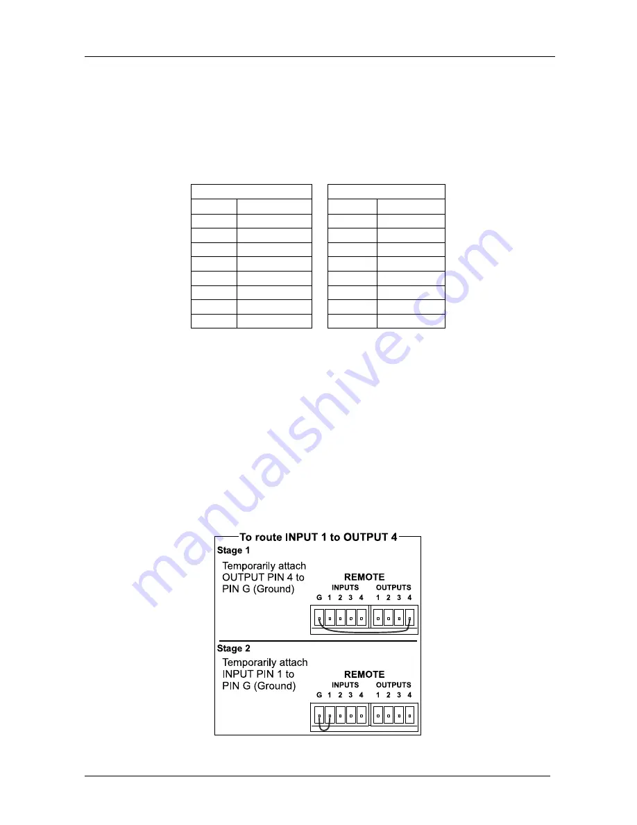
enables you to route an input to an output by remote control. For example, to 

route input 1 to output 4, as the example in Figure 8 illustrates, momentarily 

touch, firstly, output # 4 to the Ground, and then secondly, input # 1 to the 

Ground. 


Figure 8: Using the REMOTE Connector 

Summary of Contents for LTM-4x4HDSDI

Page 1: ...USER MANUAL Model LTM 4x4HDSDI 4x4 HD SDI SDI Router ...

Page 2: ... LTM 4x4HDSDI 13 7 1 Switching OUT IN Combinations 13 7 2 Confirming Settings 13 7 2 1 Toggling between the AT ONCE and CONFIRM Modes 14 7 2 2 Confirming a Switching Action 14 7 3 Storing Recalling Input Output Configurations 15 7 3 1 Storing an Input Output Configuration 15 7 3 2 Recalling an Input Output Configuration 15 7 4 Locking the Front Panel 15 8 Technical Specifications 16 9 Table of Hex...

Page 3: ...3 Machine Dipswitch Settings 8 Table 4 Crossover Cable RJ 45 PINOUT 10 Table 5 Straight through Cable RJ 45 PINOUT 12 Table 6 Technical Specifications of the LTM 4x4HDSDI 4x4 HD SDI SDI Router 16 Table 7 LTM 4x4HDSDI Hex Codes for Switching via RS 232 RS 485 16 Table 8 Protocol Definitions 17 Table 9 Instruction Codes for Protocol 2000 18 ...

Page 4: ...view The LTM 4x4HDSDI is a true 4x4 matrix switcher for standard definition high definition SDI signals that lets you simultaneously route any of the four inputs to any or all of the four outputs In particular the LTM 4x4HDSDI features Input and output signals on BNC connectors Selector buttons that automatically light up in different colors red when the LTM 4x4HDSDI detects a standard definition ...

Page 5: ...THERNET Remote contact closure for forced operation To achieve the best performance Connect only good quality connection cables thus avoiding interference deterioration in signal quality due to poor matching and elevated noise levels often associated with low quality cables Avoid interference from neighboring electrical appliances that may adversely influence signal quality and position your LTM 4...

Page 6: ...Your LTM 4x4HDSDI 4x4 HD SDI SDI Router 3 Figure 1 LTM 4x4HDSDI 4x4 HD SDI SDI Router ...

Page 7: ...ays the selected input switched to the output marked above each input Table 2 Rear Panel LTM 4x4HDSDI 4x4 HD SDI SDI Router Feature Function 12 GENLOCK BNC Connector Connect to the Genlock source 13 TERM Button Press to terminate the Genlock source 75 or release for looping 5 14 LOOP BNC Connector Connect to the GENLOCK connector of the next unit in the line 15 INPUT BNC Connectors Connect to the ...

Page 8: ...mental effect on overcurrent protection and supply wiring Refer to the appropriate nameplate ratings for information For example for fuse replacement see the value printed on the product label 5 The machine is earthed grounded in a reliable way and is connected only to an electricity socket with grounding Pay particular attention to situations where electricity is supplied indirectly when the powe...

Page 9: ... source to the GENLOCK BNC connector The LOOP BNC connector to the GENLOCK connector of the next unit in the line and release the TERM button for looping4 5 Connect a PC and or controller if required to the RS 232 port see section 6 2 and or RS 485 port see section 6 3 and or ETHERNET connector see section 6 4 6 As an option3 connect a remote dry contact switch refer to section 6 5 7 Connect the p...

Page 10: ...Connecting Your LTM 4x4HDSDI 4x4 HD SDI SDI Router 7 Figure 2 Connecting the LTM 4x4HDSDI 4x4 HD SDI SDI Router ...

Page 11: ...ntrolled when several LTM 4x4HDSDI units connect to a PC or serial controller Set the Machine on a LTM 4x4HDSDI unit via SETUP DIPS 1 2 3 and 4 according to Table 3 When using a standalone LTM 4x4HDSDI unit set the Machine to 1 When connecting more than one LTM 4x4HDSDI unit set the first machine the Master that is closest to the PC as Machine 1 dipswitches are set to OFF Table 3 Machine Dipswitch...

Page 12: ...rear panel port on the LTM 4x4HDSDI unit as Figure 4 illustrates Figure 4 Connecting a PC without using a Null modem Adapter 6 3 Controlling via the RS 485 Port To cascade up to eight individual LTM 4x4HDSDI units via RS 485 with control via a Master Programmable Remote Control system do the following 1 Connect the A and B PINS on the RS 485 terminal block port of the Master Programmable Remote Co...

Page 13: ...A Side 1 EIA TIA 568B Side 2 PIN Wire Color PIN Wire Color 1 White orange 1 White green 2 Orange 2 Green 3 White green 3 White orange 4 Blue 4 Blue 5 White blue 5 White blue 6 Green 6 Orange 7 White brown 7 White brown 8 Brown 8 Brown Pair 1 4 and 5 Pair 1 4 and 5 Pair 2 1 and 2 Pair 2 3 and 6 Pair 3 3 and 6 Pair 3 1 and 2 Pair 4 7 and 8 Pair 4 7 and 8 Figure 5 RJ 45 PINOUT This type of connection...

Page 14: ... Local Area Connection Properties window appears 5 Select the Internet Protocol TCP IP and click the Properties Button see Figure 6 Figure 6 Local Area Connection Properties Window 6 Select Use the following IP Address and fill in the details as shown in Figure 7 7 Click OK Figure 7 Internet Protocol TCP IP Properties Window ...

Page 15: ...e blue 5 White blue 6 Green 6 Green 7 White brown 7 White brown 8 Brown 8 Brown 6 4 3 Control Configuration via the Ethernet Port To control several units via the Ethernet connect the Master unit MACH NO 1 via the Ethernet port to the LAN port of your PC Use your PC initially to configure the settings see section 6 4 6 5 Controlling via the REMOTE Connector Connecting the REMOTE terminal block con...

Page 16: ...that The OUTPUT button color changes during routing according to the input button color red for standard definition or blue for high definition If an OUTPUT button is not selected that button will not illuminate If no source is connected to an INPUT that INPUT button will not illuminate 7 2 Confirming Settings Choose to work in the AT ONCE or the CONFIRM mode see section 7 2 1 When the LTM 4x4HDSD...

Page 17: ...tions now require user confirmation and the TAKE button illuminates 2 Press the illuminated TAKE button to toggle from the CONFIRM mode back to the AT ONCE mode Actions no longer require user confirmation and the TAKE button no longer illuminates 7 2 2 Confirming a Switching Action To confirm a switching action in CONFIRM mode where the TAKE button is illuminated do the following 1 Press an OUT IN...

Page 18: ...appropriate INPUT OUTPUT button the button corresponding to the setup That setup configuration will blink in the 7 segment Display The memory recalls the stored data from that reference After pressing the same memory location the second time the settings will take effect 7 4 Locking the Front Panel To prevent changing the settings accidentally or tampering with the unit via the front panel buttons...

Page 19: ... Hi Z on a BNC connector MAX OUTPUT LEVEL 800mVpp 75 ohms DATA RATE Up to 1 485Gbps CONTROLS Front panel RS 232 RS 485 ETHERNET infra red remote dry contact and panel lock POWER SOURCE Universal 100 240VAC 50 60Hz 22VA DIMENSIONS 19 inch W 7 inch D 1U H rack mountable WEIGHT 2 6 kg 5 7 lbs approx ACCESSORIES Power cord Null modem Adapter 9 Table of Hex Codes for Serial Communication Table 7 lists ...

Page 20: ...he value to be set for N5 N0 2nd BYTE Bit 7 Defined as 1 I6 I0 INPUT When switching ie instruction codes 1 and 2 the INPUT 7 bits is set as the input number which is to be switched Similarly if switching is done via the machine s front panel then these bits are set with the INPUT NUMBER which was switched For other operations these bits are defined according to the table 3rd BYTE Bit 7 Defined as ...

Page 21: ...NPUT byte 8 User defined sync 32 RGBHV seamless switching 64 Set for delayed switch 65 Execute delayed switch 66 Cancel delayed switch setting 2 5 17 18 BREAKAWAY SETTING 0 0 audio follow video 1 audio breakaway 2 8 1 0 FOLLOW mode 1 Normal mode 15 VIDEO AUDIO TYPE SETTING 0 for video 0 CV 1 YC 2 YUV 3 RGBS 4 SDI 5 CV YC 6 VGA scaler 7 DVI 1 for audio O0 0 Unbalanced audio O0 1 Balanced audio O1 0...

Page 22: ...trast 4 increase brightness 5 decrease brightness 6 increase colour 7 decrease colour 8 increase hue 9 decrease hue 16 increase H phase 17 decrease H phase 18 increase V position 19 decrease V position 24 24 INCREASE DECREASE AUDIO PARAMETER Equal to input output number whose parameter is to be increased decreased 0 all 0 increase output 1 decrease output 2 increase left output 3 decrease left out...

Page 23: ...ers it will reset according to the present power down settings NOTE 2 These are bi directional definitions That is if the switcher receives the code it will perform the instruction and if the instruction is performed due to a keystroke operation on the front panel then these codes are sent For example if the HEX code 01 85 88 83 was sent from the PC then the switcher machine 3 will switch input 5 ...

Page 24: ...he reply is the decimal value of the INPUT and OUTPUT For example for a 2216 the reply to the request to send the audio machine name would be HEX codes 7D 96 90 81 i e 128dec 22dec for 2nd byte and 128dec 16dec for 3rd byte If the request for identification is sent with the INPUT set as 3 or 4 the appropriate machine will send its software version number Again the reply would be the decimal value ...

Page 25: ... 21 To store data in the non volatile memory of the unit eg the EEPROM for saving SETUPS The EEPROM address is sent using the INPUT byte and the data to be stored is sent using the OUTPUT byte To use this instruction it is necessary to understand the memory map and memory structure of the particular machine NOTE 22 Instruction 59 and instruction 60 load data for sending to the crosspoint switcher ...

Page 26: ...P N 2900 000253 Caution Safety Warning Disconnect the unit from the power supply before opening servicing ...

Reviews: