background image


                   WISM+ DVK MANUAL 


  Version 1.00 

Page 21 


©


Laird Technology 2010


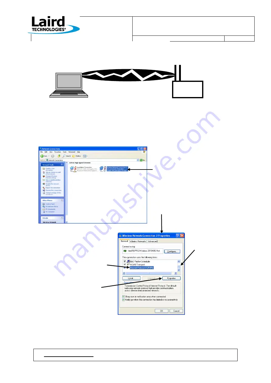
We will be setting up the following scenario… 


Since the WISM+ has been configured and reset into Ad-Hoc mode, now we have to go to the PC side and configure 
its Ad-Hoc wireless connection.   

 
Click…Start

Control Panel

Network Connections… 


 Right Click on the 
Wireless Network 
Connection and 
select “Properties”.   


The screen below will 
appear… 


First, pull the bar 
down to get to the end 
of the list 
 

Next, Select  
“Internet Protocol (TCP/IP)”  


Now click “Properties”  


WISM+ 

Dev Kit 

Ad-Hoc mode 
IP: 192.168.1.10 

Ad-Hoc mode 
IP: 192.168.1.22 

Summary of Contents for DVK-WLM400

Page 1: ...WISM DVK MANUAL Version 1 00 Page i Laird Technology 2010 DVK WLM400 402 Developer Kit Manual ...

Page 2: ...aird Technologies makes no warranty express statutory and implied or by description regarding the information set forth herein Laird Technologies reserves the right to change specifications at any time and without notice Laird Technologies products are intended for use in normal commercial and industrial applications Applications requiring unusual environmental requirements such as military medica...

Page 3: ...roughput dboard exe IS ACCESSABLE AFTER THE INSTALLATION BY Start All Programs Wism DashBoard Performance Monitor DVK Dev Kit This refers to the Developers Kit PCB which is designed to provide all power supply and interface support hardware for a WISM WAPI WISM API This is the API command language used between a host and WISM for configuration and data transfer WIF WIF exe This stands for Wism Int...

Page 4: ...N LED 7 2 5 4 SPI 7 2 6 BUTTONS 8 2 6 1 Reset Button 8 2 6 2 Restore Defaults Button 8 2 6 3 WAKEUP Button 8 2 7 CLOCK 8 2 7 1 Real Time Clock 8 2 7 2 Real Time Clock Battery 8 2 8 WISM 8 2 9 40 PIN HEADER 8 3 USING AT COMMANDS WITH PC SERIAL PORT 9 4 SOFTWARE WIF 13 4 1 SETTING UP PC PORTS FOR WIF WISM COMMUNICATIONS 13 4 1 1 Configuring PC USB port for WIF exe 13 4 1 2 Configuring PC Serial port...

Page 5: ...E TOOL IN AD HOC MODE 25 8 USING THE PERFORMANCE TOOL IN INFRASTRUCTURE MODE 27 9 USING WISM IN BRIDGE MODE W ACCESS POINT 29 10 REGULATORY CONSIDERATIONS 32 10 1 US AND CANADA 32 10 2 EUROPE 32 11 DEV KIT DESIGN 33 11 1 PCB STACK UP 33 11 2 PCB LAYOUT DRAWING 34 11 3 SCHEMATICS 35 ...

Page 6: ... Software Developer Kit source code Get familiar with the Dev Kit hardware see section This source code written in c represents a working sample of how to communicate with the WISM Use the SDK API Reference as a guide to understanding the C functions The directory of source files can be found at the following path C Program Files Laird Technologies Wism wapi There are several choices for which int...

Page 7: ...es Dev Kit PCB with a WLM400 FCC IC or a WLM402 CE WISM mounted Two Antennae installed on the Dev Kit and connected to the WISM antenna ports 120VAC 7 5VDC wall brick power adapter USB cable type A to mini for WISM Dev Kit connection to connect to a PC RS 232 serial cable female female for WISM COM port connection to a PC serial port Note an Ethernet cable is not provided ...

Page 8: ...me familiar with WISM DC POWER JACK POWER SWITCH Switching Power Supply I2C Header SPI Header Reset Button Restore Defaults Button 10 100 Ethernet Connector Host USB Device connector Real Time Clock Battery Optional Real Time Clock Host Com Port Power LED RUN LED WLAN LED WISM Input Power Jumper Ground Pads Antenna Mounting Hole Antenna Mounting Hole WISM U FL Port 2 WISM U FL Port 1 SPI LED Ether...

Page 9: ...232 levels at the connector to CMOS levels for WISM 4 DB9_DTR I 12 UART_DTR This is an output from the PC and is converted to CMOS levels to drive the WISM UART_DTR 5 input CURRENTLY THIS PIN HAS NO FUNCTION GROUND This is tied to Dev Kit GROUND 6 DB9_DSR O 8 DSR_READY When the WISM cannot take any more data all buffers are full it will assert DSR_READY 7 pin low which is translated to a high on D...

Page 10: ...M PIN WISM PIN NAME DESCRIPTION 1 SPI_REQ O 19 SPI_REQ This is an output from the WISM which is asserted low when the WISM has data to be transferred back to the host 2 GND Ground pin connected to the ground plane of the Dev Kit PCB 3 RESERVED This pin does go to a WISM port pin but has no function 4 N C This pin is not connected 5 SPI_MISO O 28 SPI_MISO This is the MISO Master In Slave Out data l...

Page 11: ...he WISM USB device pins WISM pin 4 USB_DDM and WISM pin 5 USB_DDP 2 2 6 Debug Com Port This is an RS 232 DCE serial port This port outputs internal debug information which can be used by Laird Technologies to attempt to debug WISM operations There is no hardware flow control DB9 Pin 2 is transmit data to the PC and DB9 pin 3 is receive data from the PC 2 3 RF 2 3 1 WISM U FL Port 1 2 These are the...

Page 12: ... switching power supply For normal operation only one jumper need be installed shorting an upper pin to a lower pin To make WISM current measurements remove the jumper and connect an ammeter between an upper and a lower pin To insert an external DC power input connect a power supply ground to one of the ground pads and the positive side of the power supply to one of the lower input power pins 2 4 ...

Page 13: ...he WISM WAKEUP pin is pulled to 3 3V which initiates a wake from deep sleep 2 7 CLOCK 2 7 1 Real Time Clock This is a Texas Instruments BQ32000 real time clock chip connected to the WISM I2C bus WISM API commands can be executed to both set and read the current time and date This is only required in certain situations when using WPA Enterprise security 2 7 2 Real Time Clock Battery This is the bac...

Page 14: ...gender changer not a Null Modem adapter at the WISM Dev Kit end If your PC does not have a serial port you ll need a USB to Serial converter Most USB to Serial converters will require a driver to be loaded You must first follow the instructions which came with your USB to Serial converter and install the driver as they recommend Once your serial port is in place and you know the COM port number CO...

Page 15: ... Click OK At the top HyperTerminal menu click File Properties and the following screen will appear Click on the Settings Tab and you will see this Click the ASCII Setup tab and you will see the ASCII Setup screen Select the Send line ends with line feeds checkbox This will ensure that when you press the ENTER key while typing in HyperTerminal that a Line End character is sent with the string to th...

Page 16: ...en see the following on the HyperTerminal The HyperTerminal screen shot above shows the notification from WISM WISM AT Port Ready that it has successfully booted Below the boot message you can see the W prompt sent by WISM indicating that it is ready for you to type an at xxxx command By simply pressing the ENTER key another W prompt should be displayed on the next line showing that the COM port c...

Page 17: ...TER multiple times and then the execution of an at search command Above you can see the resulting response from the WISM at search command Two access points have been found HighBluff and Pylon By typing at help and ENTER at the WISM prompt you will see a list of all of the AT commands which can be exercised Refer to the AT Command Reference for descriptions of the AT commands ...

Page 18: ... WIF WISM communications 4 1 1 Configuring PC USB port for WIF exe To use the PC USB port to communicate with the WISM Dev Kit a USB driver must be installed This driver exists on your PC after running SETUP EXE By default WIF exe will look for an active USB connection from the PC to the WISM Before starting the WIF exe software perform the following steps Set the Dev Kit power switch to the OFF p...

Page 19: ...se from WISM but the WISM host COM port will now be in WAPI mode and is compatible with the WISM API commands used by WIF exe To use WIF exe over the WISM host COM port perform the following steps Follow the steps in section Using AT Commands with PC Serial Port in order to set up your PC s serial port for communications Issue an at quit AT command using HyperTerminal and there will be no response...

Page 20: ...s Download the installer and launch it on your PC Follow the installation instructions so that it will automatically start up at boot time Stopping services which interfere with network traffic At Laird we use Symantec virus protection and network traffic monitoring Part of its job is to look for potentially harmful network traffic which might be hacking into your computer The WIF to WISM communic...

Page 21: ...reen populated with the current state saved in WISM constant memory Now go to section WIF exe Operation 4 2 2 Starting WIF exe over the PC Serial port Since WIF exe is looking for the USB connection upon launch MAKE SURE THE USB CABLE IS DISCONNECTED Make sure that you have exited AT command mode for the WISM host COM port as described in section Configuring PC Serial port for WIF exe issue the at...

Page 22: ...uring PC Ethernet port for WIF exe Power up the WISM Dev Kit or press the reset button and wait for the Run Led to begin flashing at a 1Hz rate Now launch Wif exe by clicking Start All Programs Wism Wism Config Tool You will then see WIF exe s interface selection screen as shown below Select Ethernet Select the Ethernet adapter associated your PC s wired network connection Click OK If everything i...

Page 23: ...ode It also allows selection of Infrastructure Ad Hoc mode You can set the SPI bus and UART parameters NOTE This tool reads and writes the state of the configured parameters stored in the WISM Any time you modify parameters they are written to the WISM upon exit of the WIF exe program You must then reset the WISM for them to take affect and re start WIF exe to view the changes by the configuration...

Page 24: ...icking OK and then exiting WIF exe the parameters will be saved to WISM s access point table in Non Volatile memory 4 6 Configure WISM Antenna From the WIF exe front page in the Wireless LAN section upper right click the Advanced button You will see the following WLAN Parameters window on the left By pulling down the Antenna selection box you can select U FL port 1 U FL port 2 or the diversity opt...

Page 25: ... in Ad Hoc mode or any other 802 11b device capable of creating an Ad Hoc Connection An Ad Hoc mode connection is always 802 11b Launch WIF exe using the USB connection and then select the following Select Ad Hoc Not Bridged Now click Configure and define the following Ad Hoc static network connection as shown below The first access point table entry is the only entry in the table which can be use...

Page 26: ... to the PC side and configure its Ad Hoc wireless connection Click Start Control Panel Network Connections Right Click on the Wireless Network Connection and select Properties The screen below will appear First pull the bar down to get to the end of the list Next Select Internet Protocol TCP IP Now click Properties WISM Dev Kit Ad Hoc mode IP 192 168 1 10 Ad Hoc mode IP 192 168 1 22 ...

Page 27: ... OK and then close the Network connections window Now that we have given our wireless connection a static IP address we are ready to allow the PC and WISM to join the Ad Hoc connection Click Start Connect To and then select the wireless connection indicated by the SSID Range Test Note The Dev Kit must be powered up this point with WISM in Ad Hoc mode and must be in range of the PC Press Connect an...

Page 28: ...and type command com as shown below Click OK At the DOS command prompt type ping followed by the IP address of the WISM and a network ping will be performed between the PC and the WISM over the 802 11b connection as shown below Four pings will be performed by default You can also type ping help and see all of the options allowed with the ping command You can set the number of pings to a large numb...

Page 29: ...h can communicate with the WISM over a serial connection Ensure that the HyperTerminal session is successfully communicating with WISM by executing a simple AT command DISABLE THE REMOTE COMPUTER S FIREWALL You may also have to disable your virus protection as described in section Configuring PC Ethernet port for WIF exe on the remote PC Execute the AT Ping command as shown below WISM boot message...

Page 30: ... dboard exe on the remote PC by clicking Start All Programs Wism DashBoard Performance Monitor dboard exe will capture packets measure throughput performance Since this the TX Performance tool uses a UDP socket there is no guaranteed delivery of packets as with TCP There may be more total packets transmitted from the WISM Host PC Tx Performance test than packets received on the remote PC by dboard...

Page 31: ...Y becomes ready If you do not have the serial connection click the box Ignore WISM Flow Control No DTR The number of packets successfully transmitted WIF exe s Performance TX test Transmit Status Window Once you press START in the above Transmit Test window packet transmission beings The following Transmit Status window will be displayed while the packets are being transmitted When WIF exe attempt...

Page 32: ...onfiguration There are too many combinations of the above diagram to discuss The Access Point could be a Router the Remote PC might not be connected directly to the Access Point or Router but over a network The PCs could have Static IP addresses etc Refer to section Using the Performance Tool in Ad Hoc Mode for a description of using WIF exe to transmit packets on the WISM Host PC and dboard exe o...

Page 33: ...e WISM in Infrastructure mode with Bridge Mode de selected as shown below Make sure Bridged is not selected Select Infrastructure Once Bridged is un selected and Infrastructure is selected press the configure button and set the first access point table entry to match the SSID of the access point with DHCP as shown below ...

Page 34: ...emote PC with an Ethernet cable Firewall and Virus protection may have to be disabled on both host and remote PCs Set up a shared folder on both PCs so each will be able to access the folder on the opposite PC once the wireless connection is established To set this up Make sure that both laptops have their TPC properties for the wired Ethernet connection set up to obtain an IP address automaticall...

Page 35: ...ridged and Infrastructure modes are selected press the configure button and set the first access point table entry to match the SSID of the access point with DHCP as shown below Now press Ok and then exit WIF exe and then re boot the WISM by pressing RESET or cycling power Now connect the WISM Dev Kit to the WISM HOST PC via an Ethernet cable When WISM connects to the Access point joins the wirele...

Page 36: ... mode joins the wireless network Create a large file maybe a hundred Mega Bytes and place it in the shared folder Performing a file copy to measure throughput On the opposite PC use Windows Explorer and navigate to view the shared folder on the other PC Drag and drop the large file from the remote shared drive to the desktop and time the network file transfer Now compute the throughput of the syst...

Page 37: ...es These limits are designed to provide reasonable protection against harmful interference when the equipment is operated in a commercial environment This equipment generates uses and can radiate radio frequency energy and if not installed and used in accordance with the instruction manual may cause harmful interference to radio communications Operation of this equipment in a residential area is l...

Page 38: ... Dev Kit Printed Circuit Board PCB is a 4 layer PCB made with standard FR4 material The solder mask technology is SMOBC The diagram below shows the basic PCB stack up for the 4 layer PCB PCB stack up The Ethernet PHI interface requires good PCB design practices in order to yield acceptable EMI suppression Use of ground plane which encloses noisy signals and clocks is imperative in order to produce...

Page 39: ...0 Page 34 Laird Technology 2010 11 2 PCB Layout Drawing The following is an assembly drawing of the Dev Kit PCB indicating reference designators and parts placements The corresponding schematics are shown in the following section ...

Page 40: ...WISM DVK MANUAL Version 1 00 Page 35 Laird Technology 2010 11 3 Schematics ...

Page 41: ...WISM DVK MANUAL Version 1 00 Page 36 Laird Technology 2010 ...

Page 42: ...WISM DVK MANUAL Version 1 00 Page 37 Laird Technology 2010 ...

Page 43: ...WISM DVK MANUAL Version 1 00 Page 38 Laird Technology 2010 ...

Reviews: