BL652 Development Kit
User Guide
Embedded Wireless Solutions Support Center:
http://ews-support.lairdtech.com
www.lairdtech.com/bluetooth
16
© Copyright 2016 Laird. All Rights Reserved
Americas: +1-800-492-2320
Europe: +44-1628-858-940
Hong Kong: +852 2923 0610
6.5
UART Mapping
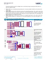
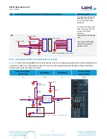
The UART connection on the BL652 series module and the FTDI IC are shown in
Table 3
.
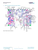
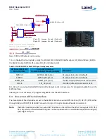
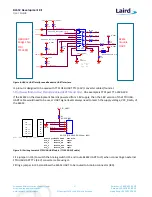
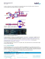
Figure 8
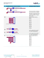
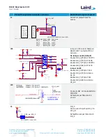
explains how
the BL652 series module UART is mapped to the breakout header connector J1. These connections are listed in
Table 3
.
Table 3: SIO/UART connections
BL652 SIO BL652 Default Function FTDI IC UART
SIO_6
UART_TX (output)
USB_RX
SIO_8
UART_RX (input)
USB_TX
SIO_5
UART_RTS (output)
USB_CTS
SIO_7
UART_CTS (input)
USB_RTS
Note:
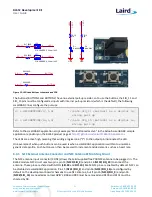
Additionally, SIO_13 (the nAutoRUN input pin on the module) can be driven by the USB_DTR output
pin of the FTDI chip. This allows testing the $autorun$ application on boot without setting the autorun
jumper on the development board. Autorun can be controlled directly from Laird’s UWTerminal using
the DTR tick box.
6.5.1
UART Interface Driven by USB
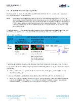
USB Connector: The development kit provides a USB Type Micro-B connector (USB1) which allows
connection to any USB host device. The connector optionally supplies power to the development kit and
the USB signals are connected to a USB-to-serial converter device (FT232R) when SW4 is set to the USB
position.
USB – UART: The development kit is fitted with a (U10) FTDI FT232R USB-to-UART converter which provides
USB-to-Virtual COM port on any Windows PC (XP or later). Upon connection, Windows auto-installs the
required drivers. For more details and driver downloads, visit the following website:
http://www.ftdichip.com/Products/FT232R.htm
.
UART Interface Driven by USB FTDI Chip: In normal operation, the BL652 UART interface is driven by the
FTDI FT232R USB-to-UART converter.
6.5.2
UART Interface Driven by External Source
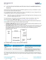
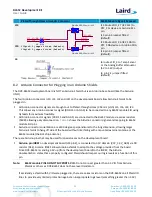
UART Interface Driven by External UART Source: The BL652 module UART interface (TX, RX, CTS, RTS) is
presented at a 2.54 mm (0.1”) pitch header (J1). To allow the BL652 UART interface to be driven from the
breakout header connector (J1), the following must be configured:
–
The development board must be powered from a DC jack (CON1) or AAA batteries (J25) and with
switch SW4 in DC position.
–
The FTDI device must be held in reset. This is achieved automatically by removal of the USB cable
(from connector USB1), placing SW4 in the DC position or fitting a jumper on J27.
–
Fit a jumper on J35 (to switch the Analog switch U15 and route BL652 UART to J1) when connecting an
external UART source (for example FTDI USB-UART TTL (3.3V) converter cable) using J1. This isolates
the BL652 UART from the on-board USB-UART FTDI device. By default, the jumper on J35 is not fitted,
so by default BL652 UART is routed to U10 FTDI FT232R USB –UART converter.
Note: The BL652 UART signal levels always need to match the supply voltage, VCC_Radio, of the
BL652.

