BL652 Development Kit
User Guide
Embedded Wireless Solutions Support Center:
http://ews-support.lairdtech.com
www.lairdtech.com/bluetooth
35
© Copyright 2016 Laird. All Rights Reserved
Americas: +1-800-492-2320
Europe: +44-1628-858-940
Hong Kong: +852 2923 0610
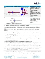
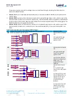
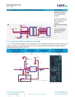
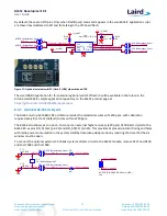
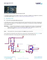
Figure 19: Current measurement schematic and PCB
There are two primary ways to measure the current consumption:
Using Ammeter – Connect an ampere meter between the two pins of J7 pins 1-2. This monitors the current
directly.
Using Oscilloscope – The open solder bridge SB2 first needs to be shorted with solder, then the on-board
10 Ohm resistor R76 which is mounted across J7 pins 1-2 can be used as current sense resistor. Connect an
oscilloscope or similar with two probes on the pins on the J7 connector and measure the voltage drop. The
voltage drop is proportional with current consumption. The 10 Ohm resistor is chosen, 10 mV equals
10mA.
There is also a third way to measure current:
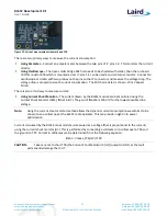
Using Current Shunt Monitor – The current drawn by the BL652 module can be monitored using the
Current Shunt Monitor (CSM), INA216 (U7). The gain of INA216 is 200 V/V for the lowest possible drop
voltage.
Note:
Using the current shunt monitor method allows the dynamic current consumption waveforms to be
shown on an oscilloscope as the BL652 radio operates. This can provide insight into power
optimization.
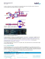
Current consumed by the BL652 series module is measured as a voltage (that is proportional to the current)
using the current shunt monitor (U7). This is performed by connecting a voltmeter or oscilloscope to TP6 and
the ground to TP7. Current in milliamps can be determined from the following equation:
I(mA) = Vmeas_TP6(mV) /100
CAUTION:
Take care not to short TP6 (the Current Shunt Monitor IC (U7)) output to GND, as that will
permanently damage the IC U7.

