background image

Operator's Manual 

– 

Lighthouse 


© 

LAI GAMES


Page 51 

Lighthouse POWER WIRING DIAGRAM 


Summary of Contents for Lighthouse

Page 1: ...READ THIS MANUAL BEFORE OPERATING THE MACHINE KEEP THIS MANUAL FOR YOUR REFERENCE LAI GAMES www laigames com...

Page 2: ...GAMES Distributor For contact details refer to the back page of this manual LAI GAMES sales laigames com www laigames com LAI GAMES LAI GAMES Copyright Notice Authorization is hereby provided to you t...

Page 3: ...th any new Software release or Service Bulletins for this Game Check our Website at www laigames com click on Product Support here you find links to all the Bulletins and Software Updates to keep your...

Page 4: ...UN TEST 14 PRIZE ARM LOCATION DIAGRAM 14 ALIGNMENT TEST 15 PROGRAMMABLE ADJUSTMENTS MODE 16 PROGRAMMABLE ADJUSTMENTS MODE DIAGRAM 16 PROGRAMMABLE ADJUSTMENTS PROCEDURE 16 PROGRAMMABLE ADJUSTMENTS QUIC...

Page 5: ...SSING PARTS 34 PARTS LOCATION DIAGRAM 34 PARTS DESCRIPTION 36 LAMPS 38 MAINTENANCE 39 INSTRUCTIONS TO FIT 90 T HANDLE LOCK 40 TO NEW TYPE COIN DOORS 40 SECTION B TECHNICAL DETAILS 43 MAINS VOLTAGE ADJ...

Page 6: ...ly connected ground line Do Not install the Game Cabinet outdoors or in areas of high humidity direct water contact dust high heat or extreme cold Do Not install the Game Cabinet in areas that would p...

Page 7: ...ions for the integrated circuit IC logic PC Boards and other connectors Insufficient insertion can damage the electrical components Only qualified personnel should inspect or test the integrated circu...

Page 8: ...y other features and user friendly adjustments that can be made to fine tune the game for maximum earning potential DESCRIPTION The Lighthouse is a one player prize redemption game where players attem...

Page 9: ...0V AC 50 60Hz single phase mains electric supply The supply must be a three wire grounded supply LOCATION REQUIREMENTS Ambient temperature between 5o C and 40o C Ambient humidity Low Ambient U V radia...

Page 10: ...will move up for positive numbers and down for negative numbers Stopping on the asterisk will have an effect that depends on Program setting P16 See program settings page 16 for details Once the Ligh...

Page 11: ...ing it all the way out 1 2 Allow a loose 3 finger gap in the hanging tie Attach the prizes securely to the Hanging Ties NOTE Be sure to allow a loose 3 finger gap in the hanging tie to ensure that the...

Page 12: ...ling the prize arm start filling the prize arm from the back and work your way towards the front START FINISH 1 Reinsert the Prize Locking pin by positioning it in the centre of the spiral making sure...

Page 13: ...he 6 Prize Arms to determine which prizes are most desired by the players You can then use the game audits to check popularity and vary the stock accordingly Varying the prize stock will also keep pla...

Page 14: ...oin Play mode where a coin or coins are inserted Or Free Play where no coins are necessary COIN PLAY The Coin Play mode is entered from Attract mode by inserting coins in any of the two coin slots on...

Page 15: ...de Diagram on next page The Test mode is also used for Clearing Game Errors If there is an active error its code will be displayed To try to clear the error code press the red test button once The err...

Page 16: ...needle to rotate two times and stop on selected position The Display counts the wheel display cycles through a pattern the level lamps light up on by one the rotating lamp runs and Sound is played TE...

Page 17: ...tabled below By activating any of the switches their code will be displayed on the 4 digit display If no switches are active then C 0 0 will be displayed CODE DISPLAY SWITCH FUNCTION SWITCH LOCATION...

Page 18: ...PCB or by manually pushing the tickets from the ticket holder through the dispenser after pulling the ticket release rod upwards EXIT The Switch Test is exited into Run Test Mode by pressing the Test...

Page 19: ...d once to start the run test mode The credit display will indicate r 0 1 the first Prize Arm and also flashing the indicator LED The Service button is then pressed again to step through each prize arm...

Page 20: ...rent positions of the needle Pressing the start button will cause the needle to move to the currently selected position Choose position U 0 1 and press the start button The needle should stop exactly...

Page 21: ...P will be displayed on the 4 digit credit display SELECT The green Service button is pressed to step through each of the adjustment configurations starting from the P P P P display P01 being the first...

Page 22: ...Asterisk Option P17 10 0 10 10 9 0 10 0 Needle Adjustment P18 0 2 0 1 2 0 Capsule Ticket Dispensing Options Used if Optional Dispenser Fitted P19 1 2 1 2 1 Game Reset Time Options P20 ON or OFF ON or...

Page 23: ...o coin mechanism 2 for each credit It can be set to either of 1 2 3 to 10 coins for one credit P05 COIN MECH 2 NUMBER of PLAYS PER CREDIT Default 01 Adjustable 1 10 This sets the number of games for e...

Page 24: ...ILL SETTINGS 1 Easiest Approx 1 Win in 20 Games 6 Medium to Hard Approx 1 Win in 200 Games 2 Very Easy Approx 1 Win in 30 Games 7 Hard Approx 1 Win in 300 Games 3 Easy Approx 1 Win in 40 Games 8 Very...

Page 25: ...r capsules paid out if the optional ticket or capsule dispenser is fitted See P13 for setting the number of mercy tickets or capsules that will be dispensed 0 Mercy System disabled no ticket or capsul...

Page 26: ...Arm 6 ON P22 Minor Arm 3 OFF P26 Minor Arm 7 OFF P23 Minor Arm 4 ON P27 Minor Arm 8 ON P28 NUMBER OF PRIZE ARM RE TRIES Default 02 Adjustable 1 8 This option controls the number of retries a user wil...

Page 27: ...mode They are A01 to A21 and their codes and values are displayed alternatively during the Audit Mode Example Code A01 will be displayed as A 0 1 and a value of 421 as 4 2 1 on the 4 digit display Or...

Page 28: ...ain from A01 to A21 until the mode is exited RESET The entire set of user audits can be reset during any of the audit configurations by holding the Start button for longer than 5 seconds The displays...

Page 29: ...rize selections on Arm 7 A08 A 0 8 No of prize selections on Arm 8 A09 A 0 9 Total No of games Won A10 A 1 0 Total No of games Lost A11 A 1 1 Total No of games Played A12 A 1 2 No of prize errors on A...

Page 30: ...stalled A09 TOTAL NUMBER OF GAMES WON This Audit displays the total number of Games Won since the audits were last cleared A10 TOTAL NUMBER OF GAMES LOST This Audit displays the total number Games Los...

Page 31: ...DITS Default positions of prize arms Prize arms 3 and 7 not installed A20 TOTAL NUMBER OF PRIZE SENSOR ERRORS ERR5 This Audit displays the total number of prize sensor errors ERR5 since the audits wer...

Page 32: ...0 1 Position Needle Stopped on for Very Last Game Played H02 H 0 2 Position Needle Stopped on for 2nd Last Game Played H03 H 0 3 Position Needle Stopped on for 3rd Last Game Played H04 H 0 4 Position...

Page 33: ...on six times H H H H will be displayed on the 4 digit display SELECT The green Service button is pressed for advancing each step through the set of Game Histories starting from the H H H H display H01...

Page 34: ...8 are set to 0 2 If the optional ticket capsule dispenser is fitted clear ticket capsule dispenser jam or replenish tickets After this push Test button once to clear error Err3 EEPROM ERROR Problem wi...

Page 35: ...s Err3 EEPROM ERROR This Error is only displayed in test mode and means that the CPU cannot read the EEPROM or is receiving errors during communication with the EEPROM The 23C16 IC on the main MCU PCB...

Page 36: ...ge 16 for Details Err7 NEEDLE INDEX SENSOR ERROR This error will only be displayed if Needle Index optic sensor on the Wheel PCB is not activating This error will usually occurs because the metal U br...

Page 37: ...s voltage AC 40Watt Level Lamps DC MOTOR CONTROL FUSE 5AMP FAST BLOW M205 TYPE This fuse is for the Tower Beacon Lamp Motor DOWN LIGHT FUSES 2 x 5 AMP FAST BLOW 3AG TYPE These fuses are for the two 12...

Page 38: ...Operator s Manual Lighthouse LAI GAMES Page 33 SECTION A SERVICE INSTRUCTIONS BE SURE TO READ THE FOLLOWING Carefully before servicing this machine A...

Page 39: ...Tower Prize Arm Mechanisms Prize Display Area Xenon Flash Units Control Panel Prize Chute Area Speakers 2 units Coin Mechanisms Coin Door Service Panel Inside Rubber Glide Leg Levelers Casters 4 unit...

Page 40: ...p Assembly DC Motor Controller PCB Prize Arms Mechanisms Level Win Lamps Tilt Switch Needle Compass Wheel Mechanism Prize Box Sensor PCB Slave Main MCU PCB AC Driver PCB Prize Box Sensor PCB Master 12...

Page 41: ...oin door START STOP BUTTON The Start button is the large Blue round illuminated button This button is used to start stop during a game and for test and program adjustments SELECT BUTTON The Select but...

Page 42: ...refer to the Parts Location diagram page 34 of this manual POWER SUPPLY The power supply is located at the back of the cabinet and is accessed from the rear of the machine It is a 12V 13A switching p...

Page 43: ...lamps mounted in the top of the prize display These are standard dichroic lamps and are accessed from the prize display through the prize display door LEVEL DISPLAY LAMPS These are 220 or 120VAC 40Wa...

Page 44: ...e cabinet taking care to remove any objects that may have fallen on the PCBs Check and tighten all fixing hardware and fasteners as required Regularly check that all the Display and Button Lamps are o...

Page 45: ...external stainless steel plate with two coach bolts as in the photo to the right This plate covers the T Handle hole and provides the two coach bolts for mounting it The photo on the left shows the n...

Page 46: ...rmally supplied with the T Handle and will need to be ordered separately For the Inner Cylinder key lock you can order a generic type to fit the T Handle And if you are using a Master locking system o...

Page 47: ...unting the T Handle Lock Cam Pop open the assembled T Handle Lock unit and rotate the handle 90 counter clockwise Using the two Coach Bolts you saved mount the T Handle onto the Coin Door Keeping the...

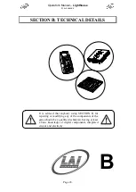
Page 48: ...N B TECHNICAL DETAILS It is advised that anybody using SECTION B for repairing or modifying any of the components of the game should be a qualified technician having at least a basic knowledge of digi...

Page 49: ...cabinet If unsure of the location of any ballasts or starters refer to Parts location diagram on page 34 of this manual These have to be removed and replaced with an equivalent wattage at you local ma...

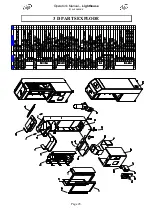
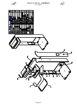
Page 50: ...Operator s Manual Lighthouse LAI GAMES Page 45 3 D PARTS EXPLODE...

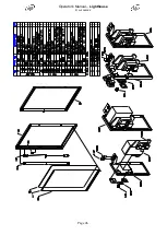
Page 51: ...Operator s Manual Lighthouse LAI GAMES Page 46...

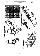
Page 52: ...Operator s Manual Lighthouse LAI GAMES Page 47...

Page 53: ...Operator s Manual Lighthouse LAI GAMES Page 48...

Page 54: ...Operator s Manual Lighthouse LAI GAMES Page 49...

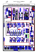
Page 55: ...Operator s Manual Lighthouse LAI GAMES Page 50 LIGHTHOUSE MAIN WIRING DIAGRAM...

Page 56: ...Operator s Manual Lighthouse LAI GAMES Page 51 Lighthouse POWER WIRING DIAGRAM...

Page 57: ...Operator s Manual Lighthouse LAI GAMES Page 52 Lighthouse OPTIONAL WIRING DIAGRAM...

Page 58: ...distributor from which the machine was purchased LAI GAMES shall have no obligation to make repairs necessitated by negligence or interference to any component by any unauthorized personal This will...

Page 59: ...NATIONAL SALES SERVICE Sales Enquires sales laigames com Product Support support mleisure co id Web site www laigames com For your nearest LAI GAMES Distributor visit our web site at http www laigames...

Reviews: