background image

Fusion 3 Table Saw \ Safety \


© 2020 Laguna Tools 


Guarding Related Warnings 

a)  Keep guards in place. Guards must be in working order and be properly mounted. A guard that 

is loose, damaged, or is not functioning correctly must be repaired or replaced. 

b)  Always use saw blade guard, riving knife and anti-kickback device for every through-cutting operation. For through- 

cutting operations where the saw blade cuts completely through the thickness of the workpiece, the guard and other 

safety devices help reduce the risk of injury. 

c)  Immediately reattach the guarding system after completing an operation (such as rabbeting, dadoing or resawing cuts) 

which requires removal of the guard, riving knife and/or anti-kickback device. The guard, riving knife, and anti-kickback 

device help to reduce the risk of injury. 

d)  Make sure the saw blade is not contacting the guard, riving knife or the workpiece before the switch is turned on. 

Inadvertent contact of these items with the saw blade could cause a hazardous condition. 

e)  Adjust the riving knife as described in this instruction manual. Incorrect spacing, positioning and alignment can make 

the riving knife ineffective in reducing the likelihood of kickback. 

f)  For the riving knife and anti-kickback device to work, they must be engaged in the workpiece. The riving knife and anti- 

kickback device are ineffective when cutting workpieces that are too short to be engaged with the riving knife and anti- 

kickback device. Under these conditions a kickback cannot be prevented by the riving knife and antikickback device. 

g)  Use the appropriate saw blade for the riving knife. For the riving knife to function properly, the saw blade diameter must 

match the appropriate riving knife and the body of the saw blade must be thinner than the thickness of the riving knife 

and the cutting width of the saw blade must be wider than the thickness of the riving knife. 


Cutting Procedures  Warnings 

a) 

Never place your fingers or hands in the vicinity or in line with the saw blade. A 

moment of inattention or a slip could direct your hand towards the saw blade and result in serious personal injury. 

b)  Feed the workpiece into the saw blade or cutter only against the direction of rotation. Feeding the workpiece in the same 

direction that the saw blade is rotating above the table may result in the workpiece, and your hand, being pulled into the 

saw blade. 

c)  Never use the miter gauge to feed the workpiece when ripping and do not use the rip fence as a length stop when cross 

cutting with the miter gauge. Guiding the workpiece with the rip fence and the miter gauge at the same time increases 

the likelihood of saw blade binding and kickback. 

d)  When ripping, always apply the workpiece feeding force between the fence and the saw blade. Use a push stick when 

the distance between the fence and the saw blade is less than 150 mm and use a push block when this distance is 

less than 50 mm. "Work helping" devices will keep your hand at a safe distance from the saw blade. 

e)  Use only the push stick provided by the manufacturer or constructed in accordance with the instructions. This push 

stick provides sufficient distance of the hand from the saw blade. 

f)  Never use a damaged or cut push stick. A damaged push stick may break causing your hand to slip into the saw blade. 
g)  Do not perform any operation "freehand". Always use either the rip fence or the miter gauge to position and guide the 

workpiece. "Freehand" means using your hands to support or guide the workpiece, in lieu of a rip fence or miter gauge. 

Freehand sawing leads to misalignment, binding and kickback. 

h)  Never reach around or over a rotating saw blade. Reaching for a workpiece may lead to accidental contact with the 

moving saw blade. 

i)  Provide auxiliary workpiece support to the rear and/or sides of the saw table for long and/or wide workpieces to keep 

them level. A long and/or wide workpiece has a tendency to pivot on the 

table’s

 edge, causing loss of control, saw blade 

binding and kickback. 

j)  Feed workpiece at an even pace. Do not bend or twist the workpiece. If jamming occurs, turn the tool off immediately, 

unplug the tool then clear the jam. Jamming the saw blade by the workpiece can cause kickback or stall the motor. 

Summary of Contents for Fusion 3

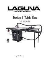
Page 1: ...OWNERS S MANUAL Fusion 3 Table Saw 36 52 Fence LagunaTools com...

Page 2: ...nes sold by Laguna include components with independent owners manuals The information contained in this publication was correct at the time of print In the interest of continuous innovation we reserve...

Page 3: ...16 Inventory List 17 Unboxing 21 Front Rail 24 Rear Rail 28 Right Extension Table 32 Rear Extension Table 34 Front Rail Pt 2 Control Switch 37 Accessory Installation 41 Maintenance 44 Troubleshooting...

Page 4: ...on this is vital to protecting your safety and preventing equipment problems To help you recognize this information we use the symbols below Please read the manual and pay attention to these sections...

Page 5: ...questions relative to its application do not use the product until you have contacted the manufacturer and we have advised you General Safety Rules FAILURE TO FOLLOW THESE RULES MAY RESULT IN SERIOUS...

Page 6: ...moment of inattention or a slip could direct your hand towards the saw blade and result in serious personal injury b Feed the workpiece into the saw blade or cutter only against the direction of rotat...

Page 7: ...the saw blade c Never hold and press the workpiece that is being cut off against the rotating saw blade Pressing the workpiece being cut off against the saw blade will create a binding condition and k...

Page 8: ...ce Accumulated sawdust is combustible and may self ignite 5 The table saw must be secured A table saw that is not properly secured may move or tip over 6 Remove tools wood scraps etc from the table be...

Page 9: ...outside of our control are Actual voltage supplied to the machine Electrical code that must be met in your local province An electrician will verify that all the demands are met to properly wire the m...

Page 10: ...certified electrician Know when to use a time delay fuse AKA Slow blow fuse Generally if the motor uses a start capacitor a time delay fuse is required This type of fuse circuit breaker will not trip...

Page 11: ...is the equipment grounding conductor If repair or replacement of the electric cord or plug is necessary do not connect the equipment grounding conductor to a live terminal Check with a qualified elec...

Page 12: ...f Cord in Feet Gauge of Extension Cord 0 6 0 6 0 6 0 6 120 120 120 120 up to 25 25 50 50 100 100 150 18 AWG 16 AWG 16 AWG 14 AWG 6 10 6 10 6 10 6 10 120 120 120 120 up to 25 25 50 50 100 100 150 18 AW...

Page 13: ...te qui n cessite l enl vement du protecteur du couteau diviseur et ou de l appareil anti recul Le protecteur le couteau diviseur et l appareil anti recul contribuent limiter le risque de blessure Veil...

Page 14: ...s le guide longitudinal et provoquer un recul Causes de recul et avertissements associ s Le recul est une r action soudaine de la pi ce due une lame pinc e bloqu e ou une ligne de coupe mal align e da...

Page 15: ...vient de l installer dans un endroit qui pr voit une place suffisante pour pouvoir manipuler facilement la pi ce quelle que soit sa taille Des endroits exigus sombres et des sols in gaux et glissants...

Page 16: ...p The saw can easily be leveled to the floor with the integrated foot pads on the right side of the base 4 After leveling the base to the foundation begin to follow the Front Rail Section 5 After the...

Page 17: ...damaged goods under the limited warranty to Laguna Tools Inc you MUST have the original packaging All claims of loss or damaged goods must be reported to Laguna Tools within 24 HOURS of delivery Pleas...

Page 18: ...d familiarize yourself with the hardware listed below Ref Description Q Installation A Counter Sunk Alan Head Screws 25mm use with hex nuts F flat washers H 7 Front Rail Assembly F3 Table Also used to...

Page 19: ...shers 8mm 8 Multiple I Hex Cap Bolt 51mm use with Nylon Lock Nuts H 4 Rear Extension Table Legs Rear Extension table J Nylon Lock Nuts 16mm 4 Rear Extension Table Legs Rear Extension table K Rubber Fe...

Page 20: ...ols Accessory Hardware Tools NOTICE The hardware and tools listed below come individually wrapped in plastic bags General Tools dual sided wrench and Allen wrenches Band clamp with hex bolt flat washe...

Page 21: ...rocedures seek assistance from an experienced professional DO NOT attempt any procedure that you feel is unsafe or that you feel you do not have the physical capability of achieving Do not cut deep in...

Page 22: ...ple to assist in completing step two 2 With another person lift the wooden crate off the wooden pallet The table saw and individually boxed accessories will be located beneath 3 Remove individually pa...

Page 23: ...eps without further assistance 2 Preferably with another person slowly walk the table saw off the wooden pallet 3 For safe assembly place the table saw in a well lit location free of any debris or obs...

Page 24: ...Reference Guide Add Required Tools Level Allen Wrenches General Wrench Troubleshooting Tips Attaching the rubber feet to the rear extension legs before attaching the legs to the front rail bracket wi...

Page 25: ...en each foot to start Later the foot may need to be loosened or tightened in order to properly level the front and rear rails Correctly installed foot NOTICE You may assemble both right extension legs...

Page 26: ...hread the flat washers and hex nuts onto the back of each counter sunk bolt 4 Use a level to ensure that the front rail is level to the table If needed you may adjust the height of the extension leg t...

Page 27: ...a lock washer onto the head side of the 30 mm hex bolts Then thread two 30 mm hex bolts through each of the left front rail s bolt holes 3 Thread a flat washer and hex nut onto the back of the 30 mm...

Page 28: ...ector hose support to the right rear rail bracket BEFORE attaching the right extension leg to the bracket will make for easier assembly Parts REF Description Q Installation Right Extension Legs now as...

Page 29: ...olt holes at the end of the right rear rail bracket 2 Using one socket head cap screw secure the right extension leg to the rear right rail bracket This will ensure that the leg does not move as the d...

Page 30: ...the right rear rail bracket s bolt holes with the bolt holes located on the back of the table as shown below 2 Thread 1 socket head cap screws and lock washer through the rear rail and table s throug...

Page 31: ...the rear rail bracket over the right and left rear rail brackets pictured below 3 Align the rear rail s bolt holes with the left and right rear rail s bolt holes as shown 4 Thread socket head cap scre...

Page 32: ...tension table s grooves are fitted snugly on the threads of the screws bolts before securing the extension table to the rear rails Parts REF Description Q Installation Right Extension Table 1 Right Re...

Page 33: ...ket 3 Place the right extension table s grooves on top of the socket head and counter sunk screws respectively Ensure that each of the four the grooves are securely rested on the threads of each of th...

Page 34: ...escription Q Installation Rear Extension Table 1 Rear Rail Assembly F3 Table Rear Extension Table Legs 2 Rear Extension Table Hardware REF Description Q Installation C Hex Cap Screw w Flat Washer long...

Page 35: ...le Securing Bolts Installed Legs Attaching the Rear Extension Table to the Table Saw 1 Locate the three through holes on the back mounting bracket of the rear extension table 2 Align these three throu...

Page 36: ...Fusion 3 Table Saw Setup Rear Extension Table 36 2020 Laguna Tools Pre installation Aligning the bracket Bolt into thread holes...

Page 37: ...t front rail from underneath the front left rail bracket This will allow the left front rail block to fit properly on the left front rail bracket Parts REF Description Q Installation Front Rail Assemb...

Page 38: ...il Pre Installation Control Switch Placement Mounting Control Switch with 2 longer hex bolts and flat washers Control Switch correctly mounted The expose bolts will fit the through holes in the fence...

Page 39: ...ugh each of the front rail s bolt holes NOTICE Only hand tighten the bolts for now 4 Pull the rail out as far as it will allow first This will allow space for the fence s nylon slider to move through...

Page 40: ...Fusion 3 Table Saw Setup Front Rail Pt 2 Control Switch 40 2020 Laguna Tools Fence fitted over the front guide rail Detailed view Front of rail showing counter sunk screws Properly Installed Fence...

Page 41: ...al Be sure the machine is off when you attempt to remove the writing knife from its position on the back of the blade Parts REF Description Q Installation Blade Guard Assembly 1 Boxed Individually Dus...

Page 42: ...ok s hex bolts through the fence hook s bolt holes 3 Thread the hex bolts through the bolt holes on the back of the table saw 4 Tighten the hex bolts with the general wrench Fence Hook Installation Fe...

Page 43: ...Table Saw Setup Accessory Installation 2020 Laguna Tools 43 From Top Down A Arbor Wrench B Miter Gauge C Riving Knife D Blade Guard Hook E Dust Hose Wrapping Hook Your F3 Table Saw is now properly as...

Page 44: ...loosen the Hex Nut C Fig B then turn the 90 stop screw D Fig B under the table by Hex wrench Turn the hand wheel until the blade is at 90 to the table surface Then re tighten the 90 stop screw Hex nu...

Page 45: ...be tilted to the left anywhere from 0 90 to the table to 45 WARNING TO LIMIT YOUR EXPOSURE TO THE BLADE AND ALSO TO MAXIMISE THE EFFECTIVENESS OF THE ANTI KICKBACK PAWLS WHEN USING THE RIVING STYLE S...

Page 46: ...BLE PARALLEL TO BLADE Fig F Fig G Fig H STEP 1 Loosen 4 bolts as shown STEP 2 Adjust table parallel to T Slot miter slot by pivoting table Use a ruler to measure from blade to T Slot at the front and...

Page 47: ...Fusion 3 Table Saw Troubleshooting 2020 Laguna Tools 47 ADJUSTING 90 STOP...

Page 48: ...Fusion 3 Table Saw Maintenance 48 2020 Laguna Tools ADJUSTING 45 STOP...

Page 49: ...ected regularly for cracks cuts and general wear If damage is found replace the belt Bearings All bearings are sealed for life and do not require any maintenance If a bearing becomes faulty replace it...

Page 50: ...Fusion 3 Table Saw Maintenance 50 2020 Laguna Tools DRO POWER CONNECTION TEST CHECK If DRO does not power up or is inconsistent please check the following...

Page 51: ...Fusion 3 Table Saw Troubleshooting 2020 Laguna Tools 51...

Page 52: ...locate shim machine 5 Re tighten replace arbor pulley 6 Adjust tension of replace belt 7 Realign replace shaft pulley setscrew and key 8a Replace arbor housing bearings replace arbor 8b Test by rotati...

Page 53: ......

Page 54: ...mm Overall Depth front to back 39 3 4 1009 mm 39 3 8 1000 mm 56 1425 mm 56 1425 mm Overall Height 46 1168 mm 47 1193 mm 47 1193 mm 47 1193 mm Power Requirement 110V 230V Single Phase 60 Hz wired 110V...

Page 55: ...torage Blade Changing Tool Included Included 10 x 60T Carbide Tipped Blade Integrated Tool Storage Premium Arbor and Motor Bearings Included 10 x 60T Carbide Tipped Blade Premium Arbor and Motor Beari...

Page 56: ...Hi Lo Face Camlock T Shape w European Hi Lo Face Camlock T Shape w European Hi Lo Face Fence Size Length 33 1 2 850 mm 33 1 2 850 mm 33 1 2 850 mm 33 1 2 850 mm Fence Size Width 9 7 8 250 mm 9 7 8 25...

Page 57: ...Dust Port Size 1 1 2 38 1 mm 1 1 2 38 1 mm 1 1 2 38 1 mm 1 1 2 38 1 mm Dust Collection CFM Requirement min 400 CFM 400 CFM 400 CFM 400 CFM Dust Collection Static Pressure 5 H20 5 H20 5 H20 5 H20 FUSI...

Page 58: ...Cord Plug Power Cord Included Yes Yes Yes Yes Power Cord Length 6 ft 6 ft 6 ft 6 ft Power Cord Gauge 14 AWG 14 AWG 14 AWG 14 AWG Plug Included Yes Yes Yes Yes Switch Type ON OFF Push Button Switch w L...

Page 59: ...an Warranty 1 Year 1 Year 1 Year 1 Year Approximate Assembly Setup Time 1 Hour 1 Hour 1 Hour 1 Hour Serial Number Location ID label on cabinet ID label on cabinet ID label on cabinet ID label on cabin...

Page 60: ...Fusion 3 Table Saw Wiring Diagram 52 2020 Laguna Tools Wiring Diagram Switch Plate DRO...

Page 61: ...Fusion 3 Table Saw Replacement Parts Diagram 2020 Laguna Tools 53 Replacement Parts Diagram Cabinet...

Page 62: ...Fusion 3 Table Saw Replacement Parts Diagram 54 2020 Laguna Tools Internal...

Page 63: ...Fusion 3 Table Saw Replacement Parts Diagram 2020 Laguna Tools 55 Blade Guard Miter Gauge...

Page 64: ...Fusion 3 Table Saw Replacement Parts Diagram 56 2020 Laguna Tools 36 Rails Fence Guard Outfeed Table...

Page 65: ...Fusion 3 Table Saw Replacement Parts Diagram 2020 Laguna Tools 57 52 Rails Fence Guard Outfeed Table...

Page 66: ...615 Frictional Wheel 1 15 250472 621 Plastic Set Screw M12 1 75 2 16 000004 306 Hex Screw M10 1 5x50 1 17 230282 615 Ball 1 18 922141 000 Compress Cam Assembly 1 19 250471 621 Frictional Plate 2 20 00...

Page 67: ...30336 615 Bolt 1 9 171378 904 Anti Kick Finger Left 1 10 280162 901 Spring 1 11 251311 615 Block 1 12 360864 000 Pin 1 13 360865 901 Spreader Shaft 1 14 280160 901 Spring 1 15 010204 000 Retaining Rin...

Page 68: ...xtension Table 2 6 924397 000 Table Insert Assembly 1 7 051368 000 Table 1 8 006001 049 Flat Washer 8 5 16x2 0 22 9 000003 104 Hex Screw M8 1 25x20 12 10 051370 000 Up down Bracket 1 11 008006 100 Hex...

Page 69: ...000 Upper Trunnion 1 40 002601 107 Locking CAP screw M8 1 25x25 2 41 174773 000 Fixing Plate 1 43 251398 615 Dust Hood 1 44 002002 101 Round Head Phillip Screw M5 0 8x8 5 46 174325 156 Arbor Lock Han...

Page 70: ...100 Spring Washer 8 2x15 4 15 75 006001 078 Flat Washer 10 5x19x1 5 1 76 190273 901 Bushing 1 77 000202 101 SET Screw M5 0 8x5 4 78 051469 000 N A 1 79 011004 103 Spring Pin 6x25 2 80 175012 156 Point...

Page 71: ...5 6 109 000003 115 Hex Screw M8 1 25x55 1 110 020003 000 Strain Relief SB7R 3 1 111 006001 001 Flat Washer 4 3x10x1 0 2 112 000302 102 Pan Head Screw M4 0 7x8 2 113 004001 101 Knob 5 16 18x3 4 2 114 0...

Page 72: ...000004 112 Hex Screw M10 1 5x45 4 3 049201 101 Hex Screw w Flat Washer M8 1 25x16 13Bx6 5H 3 5 174780 308 Support Plate 1 6 001102 505 Round Hear Tapping Screw M4 1 59x16 16 7 440099 000 Rear Table 1...

Page 73: ...6 5H 10 4 000704 102 Flat Head Hex Screw M8 1 25x25 4 5 230041 000 Leveling foot 2 7 440077 000 Right Table 1 8 173139 902 Brace 4 9 230086 901 Tapping Screw 8 10 190205 308 Leg 2 7 924969 000 Connect...

Page 74: ...or Wrench 1 145 175013 000 Stand 1 152 012002 005 Key 4x4x12 2 153 049201 101 Hex Screw w Flat Washer M8 1 25x16 13Bx6 5H 1 160 043322 000 O Ring P11 1 161 002402 102 Round Head Lock Screw w Washer M5...

Page 75: ...1 1 042620 016 Dust Hose 1 5 3700mm I D 1 2 174887 904 Brace 1 5 850913 000 Hardware Bag for 52 Over Head Guards 1 1 042622 003 Clamp 30 45 mm I D 2 2 001803 103 CAP Screw w Spring Washer M8 1 25x25 8...

Page 76: ...Fusion 3 Table Saw Replacement Parts Table 68 2020 Laguna Tools...

Page 77: ......

Page 78: ...he product from the receipt date The original purchaser must present the original receipt as proof of purchase Shipping Damage Laguna Tools and the purchasing customer is not responsible for damage or...

Page 79: ...hipping documents Note all damages on the carrier s shipping documents Note any missing or broken packaging on the carriers shipping documents All product shortage claims must be made to Laguna Tools...

Page 80: ...shipping documents Note all damages on the carrier s shipping documents Note any missing or broken packaging on the carriers shipping documents All product shortage claims must be made to Laguna Tool...

Page 81: ...one 1 949 474 1200 South Carolina 825 Bistline Dr Ste 101 West Columbia SC 29172 U S A Phone 1 800 234 1976 Minnesota 5250 West 74th St Edina MN 55439 U S A Phone 1 949 474 1200 LAGUNA EUROPE Walker R...

Reviews: