background image

Page 

13

 of 

23


Cha

p

ter:


6


U

n

d

ers

ta

n

d

in

g W

o

rk

 Co

o

rd

in

at

e sys

te

m

13


UNDERSTANDING WORK COORDINATE SYSTEMS 


Machine Coordinates(Workpiece 0) 

o


Machine origin is established using home switches.  

o


Tool positions and TTO switch location are set relative to machine coordinates

.    

o


Press

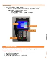
 MENU + ZRN/0

 to switch to workpiece 0.


Hold down the 

MENU

 + 

1-9 buttons

 to move between work 

coordinate systems. 


In the picture to the right the active work coordinate system is 
"Workpiece 2"  


Transitioning between workpieces will, in turn transition between 
X, Y, and Z offsets made in each Workpiece.  


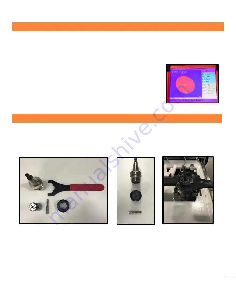
TOOL CONE SETUP 

1.


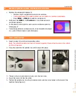
Select a router bit and its corresponding collet. 

Note. The collets & spindle nut must be cleaned regularly. Ensure that the slots in the collets 
are free of sawdust.  

2.


Press the collet into the spindle nut until it snaps into place.  


3.


Thread on the nut and collet by hand, onto the tool cone. 

4.


Insert the router bit into the collet.  

5.


Tighten the spindle nut. Use the provided wrench and tool cone holder on the back of the 
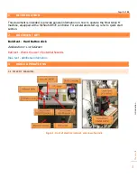
machine frame(figure 2). 


Summary of Contents for Smartshop M

Page 1: ...for Smartshop machines equipped with the RichAuto B57E Basic operations Quick Start Mutli Tool Programs Creating a G code le with V carve Maintenance and Troubleshooting Installation Outline Default...

Page 2: ...m 10 5 1 Setting tool offsets 10 5 2 Setting XY work origin 11 5 3 Setting Z work origin 11 5 4 Run program 12 6 Understanding Work Coordinate systems 13 7 Tool Cone Setup 13 8 Maintenance and Trouble...

Page 3: ...hine equipped with a RichAuto B57E controller For accelerated start up refer to quick start section 2 DOCUMENT KEY Bold text Hard Button click Italicized text List Selection Red text Warns the user of...

Page 4: ...Operations 4 Figure 2 Front and rear view of machine 3 2 TURNING ON THE MACHINE 1 Turn the rotary switch to the ON position 2 Turn the key to the ON position 3 Press the Control Power ON OFF button l...

Page 5: ...This resets your machine coordinates origin relative to the home switches and flags 2 The tool locations are relative to the machine origin The default selection is All axis home 1 Press REF OK to be...

Page 6: ...ically Using the Tool Switch button Press ToolSwitch button Use up and down Y buttons to highlight tool selection Press REF OK button 4 QUICK START SECTION This section is a work flow from turning the...

Page 7: ...ernal memory When running a program directly from a USB memory transfer is less reliable It is recommended to store the program in the controller s internal memory a MENU Menu Function User Interface...

Page 8: ...1 button then release both buttons 9 Verify which tool cone is currently in the spindle and compare to the CurSpindl parameter on the controller run screen figure 4 a If current tool number is not too...

Page 9: ...tton c On the controller you will see the Z axis coordinate go to zero figure 4 12 Press REF OK button a This will retract the spindle to a safe starting location 13 Put on your SAFETY GLASSES and run...

Page 10: ...ined at the time of program creation o Change to workpiece 1 and tool 1 see section 3 5 o Verify Workpiece 1 o Verify CureSpindl Spindle 1 and tool 1 is in the spindle o Manually jog the spindle into...

Page 11: ...ectric s V Carve software it is called the XY datum position o Once the spindle is in position press the XY 0 button to set the XY origin point o On the controller you will see the X and Y axis coordi...

Page 12: ...om a USB memory transfer is less reliable It is recommended to store the program in the controller s internal memory a MENU Menu Function User Interface REF OK b Machine Configuration REF OK c Scroll...

Page 13: ...the active work coordinate system is Workpiece 2 Transitioning between workpieces will in turn transition between X Y and Z offsets made in each Workpiece 7 TOOL CONE SETUP 1 Select a router bit and i...

Page 14: ...reset the controller s machine coordinates relative to the position of the home switches and flags o Verify the controller is in machine coordinates workpiece 0 If not press MENU ZRN 0 to change to m...

Page 15: ...1 2 and 3 o Verify your work o Test the tool change without a tool cone o Test the tool change with a tool cone without a router bit 8 2 TOOL TOUCH OFF TOOLSETTINGZ ADJUSTMENT o If the ToolSettingZ p...

Page 16: ...Page 16 of 23 Chapter 9 Creating a G Code file 16 9 CREATING A G CODE FILE Create a new project Sketch your part...

Page 17: ...Page 17 of 23 Chapter 9 Creating a G Code file 17 Open Toolpath tab and select a toolpath function Edit toolpath parameters...

Page 18: ...Page 18 of 23 Chapter 9 Creating a G Code file 18 Edit tool parameters Visually verify that your toolpath is correct...

Page 19: ...Page 19 of 23 Chapter 9 Creating a G Code file 19 Save Toolpath o As shown below the Smartshop M is compatible with the Laguna IQ ATC mm post processor...

Page 20: ...Page 20 of 23 Chapter 9 Creating a G Code file 20 Inspect the g code file It is always a good practice to first run a program in the air without any material until a work flow is established...

Page 21: ...Page 21 of 23 Chapter 10 Appendix 21 10 APPENDIX 10 1 HITECO SPINDLE PNEUMATIC SPECIFICATIONS Model QD 1F 4 12 24 I30 NC CB BT...

Page 22: ...psi Vacuum Pumps Vacuum pumps will vary between machines o Refer to the vacuum pump electrical tag for correct wiring o Run the appropriate gauge wire from the vacuum pump to the electrical cabinet o...

Page 23: ...Page 23 of 23 Chapter 10 Appendix 23 10 2 DEFAULT MACHINE SETTINGS...

Page 24: ...ations subject to change Machines may be shown with optional accessories 2018 Laguna Tools Inc LAGUNA and the LAGUNA Logo are the registered trademarks of Laguna Tools Inc All rights reserved 2072 Alt...

Reviews: