background image


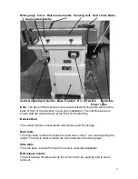
Dust chute 

The dust chute takes a 4 inch dust hose.  
 

Sanding belt 

The sanding belt is 

89 in X 6 in [2260mm X 152mm]


Fence 

The fence is secured to the main table with two T bolts. The fence has two slots 
that allow it to be adjusted to suit the width of the job. 
  

Vertical adjustment 

The table can be adjusted vertically by turning the vertical adjustment handle. 
 

Angle adjustment 

The angle between the table and the sanding belt can be adjusted. To adjust, 
loosen the clamping handle and then move the head to the required angle and 
reclamp.  
  

Motor 

The motor provides drive to the sanding belt. 
 

Power cabl. 

The machine is provided with a cable and plug.  

 
On / off switch 

The red emergency switch latches shut once pressed and has to be released 
before the sander can be restarted.  

 
Miter gauge 

The miter gauge is provided with adjustable stops for, - 45, 0, and +45 degrees. 


Summary of Contents for PRO SERIES

Page 1: ...E SANDER MANUAL LAGUNA TOOLS 2072 Alton Parkway Irvine California 92606 Ph 800 234 1976 www lagunatools com 2018 Laguna Tools Inc LAGUNA and the LAGUNA Logo are the registered trademarks of Laguna Too...

Page 2: ......

Page 3: ...dge sander 7 Parts of the oscillating edge sander 7 What you will receive with the oscillating edge sander 10 Where to locate your oscillating edge sander 12 Tools that you will need to assemble the s...

Page 4: ...butor Read the following carefully and fully before operating the machine 1 Keep the working area clean and ensure adequate lighting is available 2 Do not wear loose clothing gloves bracelets necklace...

Page 5: ...empted by others Laguna Tools Inc is not responsible for additional tools or modifications sold or performed other than from by Laguna Tools Inc on any Laguna Tools Inc machine Warranty maybe voided u...

Page 6: ...king invoice and shipping documents supplied by the driver Ensure that there is no visible damage to the packing or the machine You must do this prior to the driver leaving All damage must be noted on...

Page 7: ...iate sections of this manual Introduction to your oscillating edge sander This machine is designed to give you years of safe service Read this owner s manual in its entirety before assembly or use Ide...

Page 8: ...The main table is made from cast iron and has a miter T slot running along the length The slot is used to clamp the fence and also the miter gauge Side table The side table is made from cast iron and...

Page 9: ...the vertical adjustment handle Angle adjustment The angle between the table and the sanding belt can be adjusted To adjust loosen the clamping handle and then move the head to the required angle and...

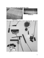
Page 10: ...10 What you will receive with the oscillating edge sander Sander box Cabinet box Belt release handle Tracking adjuster Vertical adjuster handle Cabinet feet...

Page 11: ...11 Knobs and screws Stop Miter gauge End table support rod Dust chute panel End table support End table Cabinet base Cabinet front Cabinet back Cabinet side...

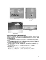
Page 12: ...a at the front of the machine suitable for comfortable working 2 There should be sufficient area at the back of the machine to allow access for adjustments and maintenance to be conducted 3 Adequate l...

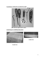
Page 13: ...13 Tools that you will need to assemble the sander Wrench 12 mm Allen wrench supplied with sander Unpacking your oscillating edge sander Sander box Cabinet box...

Page 14: ...k professional assistance Do not attempt any procedure that you feel is unsafe or that you do not have the physical capability of achieving Assembly and setup Assembling the sanding head to the cabine...

Page 15: ...s Do not fully tighten the bolts Cabinet side with feet fitted Cabinet side fitted to sanding head Cabinet side fixing bolt Cabinet back Cabinet base fixing holes 4 Fit the cabinet back Do not fully t...

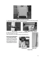
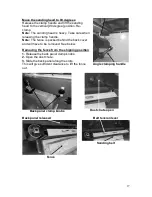
Page 16: ...tting on the cabinet 8 Move the sander so that it is standing on the cabinet 9 Fit the handle to the door 10 Fit the door to the cabinet hinges and insert the pins Remove the sanding belt The sanding...

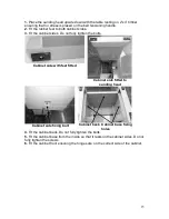
Page 17: ...Note The fence is packed behind the back cover and will have to be removed See below Removing the fence from the shipping position 1 Release the back panel clamp knobs 2 Open the dust chute 3 Slide t...

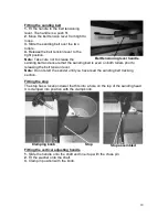
Page 18: ...s even on both rollers prior to releasing the belt tension lever Note Do not start the sander until you have read the sanding belt tracking section Fitting the stop The stop has a location dowel that...

Page 19: ...on the shaft is lined up with the clamp knob If the shaft is not clamped on the flat it will damage the shaft and it will not slide vertically 3 Slide the end table onto the support shaft and clamp in...

Page 20: ...miter gauge has a T nut that fits into the table T slot The handle clamps the miter gauge at the angle that is selected The miter gauge has a stop that when flipped into the up position lines up with...

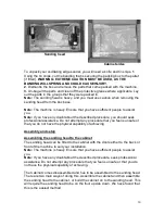
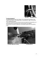
Page 21: ...anding belt is running either too high or too low the belt is adjusted as follows Loosen the clamping knob and adjust the tracking adjustment handle either up or down depending on the direction that t...

Page 22: ...ne single phase 220V It is recommended that you use a 30 amp main breaker Note A qualified electrician must carry out the installation Cleaning the machine Remove the rust protection grease with WD 40...

Page 23: ...belt direction arrows are correct they can be found on the back of the belt If the belt is fitted with the direction arrows facing in the wrong direction the belt will break The correct direction is t...

Page 24: ...a very rare occurrence as the machine is designed to fail safe If it should occur and you cannot fix the fault seek professional assistance The machine must be disconnected from the power and never ru...

Page 25: ...elt with belt cleaning stick or replace the sanding belt 3 Job held on the sanding belt too long Glazed sanding belt 1 Stock is wet Dry the stock or replace stock with dry stock 2 High resin content o...

Page 26: ......

Page 27: ......

Page 28: ......

Page 29: ......

Page 30: ......

Page 31: ...ations subject to change Machines may be shown with optional accessories 2018 Laguna Tools Inc LAGUNA and the LAGUNA Logo are the registered trademarks of Laguna Tools Inc All rights reserved 2072 Alt...

Reviews: