background image


21

Adjusting the feed rollers. 

The table rollers come factory set 1/8" below the cutter head to suit the planer 
function. When moulding, the feed rollers have to be adjusted to suit the job. It is not 
possible to be accurate in determining the feed roller height, as this will depend on 
the profile that is being used. A good rule of thumb is to set the rollers 1/4" below the 
cutter head and fine tune as required. 
 

Checking the height of the rollers. 
1. 

Place a piece of hardwood on the table. 

2. 

Bring the table up until it just touches the in- and out-feed rollers. Note the height 

reading. 

3. 

Bring the table up until it just touches the cutter blade (the rollers are spring 

loaded and will move up). Note the height. 

4. 

The difference between the two readings is the distance the rollers are lower than 

the cutter blade. 
 

Checking that the rollers are parallel to the table. 
1. 

Place a piece of parallel hardwood approximately 1-inch wide on the table under 

the in-feed roller at one end. 

2.

 Bring the table up until the wood just touches the roller. 

3.

 Move the wood to the other side under the same roller and check that it just 

touches the roller. 

4.

 If there is a difference, the roller height should be adjusted. 

5. 

Repeat for the other roller. 


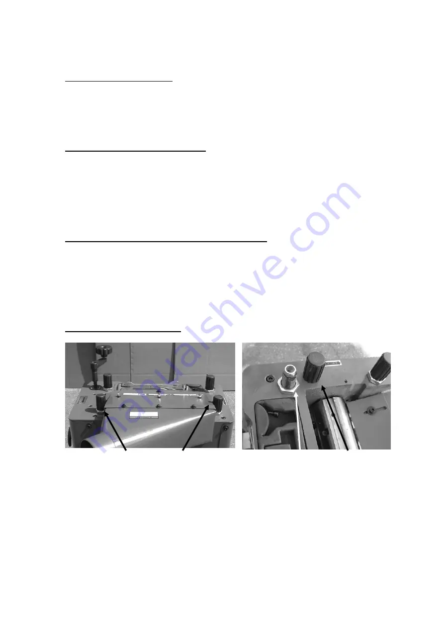
Adjusting the roller heights. 


Roller height adjusters   

Lock nut            Cap 

1.

 Unscrew the caps and remove. 

2. 

Loosen the lock nut. 

3.

 The threaded shaft has flats to suit the wrench supplied. Adjust the shaft to suit 

the adjustment required. 

4.

 Tighten the lock nut and replace the cap. 

Note.

 There is a nut on the top of the threaded shaft. Do not loosen the nut, as this 

adjusts the spring pressure and is factory set. 

Summary of Contents for MPL1301-0130

Page 1: ...TOOLS 2072 Alton Parkway Irvine California 92606 Ph 800 234 1976 www lagunatools com 2018 Laguna Tools Inc LAGUNA and the LAGUNA Logo are the registered trademarks of Laguna Tools Inc All rights rese...

Page 2: ......

Page 3: ...planer 7 Introduction to your planer 7 What you will receive with the planer 8 Parts of the planer 9 Where to locate your planer 10 Unpacking your planer 11 Assembly and setup 12 Running and adjusting...

Page 4: ...istributor Read carefully before operating the machine 1 Keep the working area clean and be sure adequate lighting is available 2 Do not wear loose clothing gloves bracelets necklaces or ornaments Wea...

Page 5: ...empted by others Laguna Tools Inc is not responsible for additional tools or modifications sold or performed other than from by Laguna Tools Inc on any Laguna Tools Inc machine Warranty maybe voided u...

Page 6: ...ffect the level of ambient noise It is possible that exposure level limits will vary from country to country Specification sheet Machine MPL3000 0120 13 Planer Moulder Motor 2 HP Planer table size 17...

Page 7: ...s a finish without lines and this also allows the insertion of the moulding blades into the same cutter head Additional Instructions for the use of planer moulder Like all machines there is danger ass...

Page 8: ...8 What you will receive with the planer 1 2 3 4 5 6 7 8 9 10 1 Roller support plates 2 Guides 3 Rollers 4 Dust chute 5 Leveling feet 6 Gear box handle 7 Gibs 8 Screws 9 Guide support rod 10 Handles...

Page 9: ...9 Parts of the planer moulder 6 7 1 2 3 4 5 9 8 10 11 12...

Page 10: ...ute A 4 inch diameter dust chute is provided The dust chute must be connected to a dust collector with a minimum capacity of 1000 c f m The machine produces a lot of sawdust and wood chippings the str...

Page 11: ...se to power source and dust collection Unpacking your machine Boxed machine Box removed Side panel removed parts inside Pallet securing bolts To unpack your machine you will need tin snips knife and a...

Page 12: ...you do not have the physical capability of achieving With two or more people move the machine so that the base of the machine is over the edge of the pallet Tilt the machine away from the pallet so t...

Page 13: ...ide of the table both in and out feed sides Do not fully tighten 2 Fit the support rollers to both in and out feed sides of the machine 3 Using a straight edge adjust the rollers level with the table...

Page 14: ...e lock nuts Fitting the guides Guide support shaft Guides Fit the guide support shaft to the in and out feed sides of the machine Attach the guides and secure with the clamping screw knobs Fitting the...

Page 15: ...do not want it to come off during production Note You will need a dust collection system with a minimum of 1000 cubic feet per minute capacity The stronger the dust collection the better as the machi...

Page 16: ...or each blade Gib Blade 3 The gibs clamp the cutter blade and have jack screws that force the gibs vertically The gib and slot in the cutter head are tapered and the vertical movement clamps the blade...

Page 17: ...that there is very little clearance between the gib and the blade but ensure that the blade is not clamped 4 Hold the setting jig on the cutter head with the raised portion over the blade Raise the cu...

Page 18: ...y down onto the bottom of the cutter head slot while the edge of the blade is just touching the setting jig and tighten the gib jacking screws 5 Repeat for the other blades 6 Adjust the red chip break...

Page 19: ...nd or correct a fault must be conducted with the power disconnected Note The stop button when pressed in with remain in the off position until reset To reset the stop button unlatch the cover Check th...

Page 20: ...be adjusted to the same dimension Adjusting the drive belts The drive belts should be checked after running the machine for approximately 10 hours The belts embed into the pulleys and will slacken of...

Page 21: ...fference between the two readings is the distance the rollers are lower than the cutter blade Checking that the rollers are parallel to the table 1 Place a piece of parallel hardwood approximately 1 i...

Page 22: ...hes the cutter head not the blade 3 Remove the wood and check the other end of the cutter head Both ends should be the same 4 If both sides are the same then no adjustment is required and in all proba...

Page 23: ...any excess and buff with a dry polishing cloth This will reduce the likelihood of rust forming and reduce the friction on the tables as the wood is machined 2 Check cutter blades for chips and dullne...

Page 24: ...as it tends to dry and therefore will attract less sawdust and dirt Lubricate the drive chains and cogs Troubleshooting and fault finding Problem Cause Corrective action Motor will not start or fuses...

Page 25: ...conflicting grain direction in wood 1 Inspect job for knots and grain direction only use good material 2 Nicked or chipped blades 2 Replace affected blades 3 Taking too of a deep cut 3 Take smaller c...

Page 26: ...ressure 1 Reset feed rollers 2 Motor belt slippage 2 Re tension drive belts 3 Table dirty 3 Clean table 4 Feed rollers worn 4 Replace feed rollers Tapered cut 1 Table not parallel to cutter head 1 Res...

Page 27: ...27 Electrical drawing...

Page 28: ...28 Exploded view drawings...

Page 29: ...29...

Page 30: ...30...

Page 31: ...31 Copyright 2010 Laguna Tools Inc Warning no portion of these materials may be reproduced without written approval from Laguna Tools Inc All documentation subject to change without notice...

Page 32: ...ations subject to change Machines may be shown with optional accessories 2018 Laguna Tools Inc LAGUNA and the LAGUNA Logo are the registered trademarks of Laguna Tools Inc All rights reserved 2072 Alt...

Reviews: