Clutch inspection
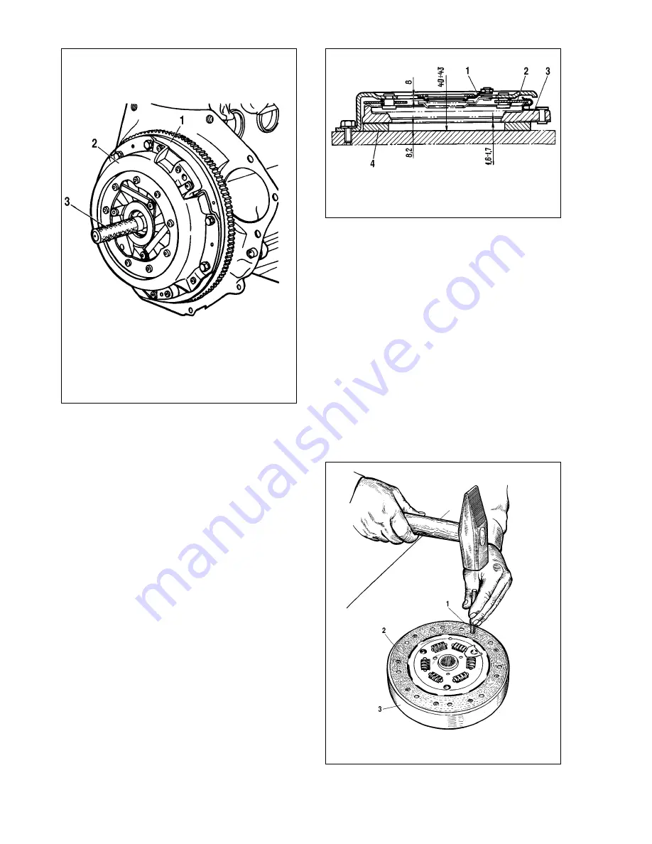
The inspection of the clutch is carried out on a bench, which
simulates the engine flywheel and has a metal intermediate ring
4 (fig. 3-5) with thickness of 8.2 mm simulating the clutch disc.
Having fixed the clutch cover, make four release strokes equal to
8-9 mm. The release stroke of 8 mm should correspond to the
travel of the pressure plate within 1.6-1.7 mm (permitted mini-
mum - 1.4 mm).
The distance from the rig base to the working surface of the
thrust flange friction washer should be 40-43 mm. During engine
operation due to wear of the clutch disc surfaces this size
increases. If it will reach 48 mm or the travel of the pressure plate
will be less than 1.4 mm, renew the clutch cover in assembly with
the pressure plate.
The clutch disc friction linings should be replaced at any signs
of cracks, reduction of distance between the rivet and the work-
ing surface up to 0.2 mm, and also at one-side scuffings. To
repair the clutch disc and replace the friction linings use tool
67.7822.9529 (fig. 3-6).
Flared rivets should have no breaks. The runout of the friction
lining working surface should not exceed 0.5 mm. If this value is
exceeded, straighten the disc (fig. 3-7) or replace with a new one.
Also replace the clutch disc assembly in case of cracks on the
clutch disc or the damper springs.
Master and slave cylinders - removal and refitting
First, drain working liquid. To do this, attach one end of the
hose to bleeder 9 (see fig. 3-3) on the slave cylinder, and the
other end place in a clean reservoir; unscrew bleeder 9 by 1/2-3/4
turn and depress the pedal several times until all liquid will be
removed from the hydrosystem, then disconnect the tubes
between the master and the slave cylinders, disconnect the
return spring 7, remove the pin from the pushrod end, and the
slave cylinder, having prior undone two fastening bolts.
To remove the master cylinder undo two nuts, with which it is
pinned to the pedal bracket, and disconnect the flexible hose
from the reservoir.
To refit the master and slave cylinders the above described
operations are executed in reverse order.
After filling with working liquid, bleed the system.
61
Fig. 3-4. Centering the clutch disc with tool A.70081:
1 - flywheel; 2 - clutch assembly; 3 - tool A.70081
Fig. 3-5. Clutch check:
1 - pressure plate thrust flange; 2 - central diaphragm spring; 3 - clutch disc;
4 - ring
Fig. 3-6.Replacing the clutch disc friction linings:
1 - tool 67.7851.9500; 2 - clutch disc; 3 - fixture 67.7822.9517
Summary of Contents for Niva 4x4
Page 80: ...135 ...
Page 81: ...136 ...


