INSTALLER
’S MANUAL
RULLY
Page 18 of 40 – US –
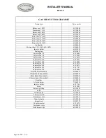
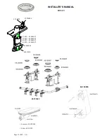
GAS CIRCUIT DIAGRAMME
Designation
Part number
Burner cap 1,5 kW
65.330004
Burner cap 3,0 W
65.330005
Burner cap 4,0 kW
65.330006
Burner cap 5,0 kW
65.330007
Burner bowl 1,5 kW
65.640008
Burner bowl 3,0 kW
65.640004
Burner bowl 4,0 kW
65.640005
Burner bowl 5,0 kW
65.640006
Air Shuttler
65.080005
Mixing tube (1,5-3,0-4,0 & 5,0 kW)
65.064007
Injector holder
65.033018
Sealing ring
65.430007
Injector Dia. 65
65.14964
Injector Dia. 90
65.14969
Injector Dia. 95
65.14970
Injector Dia. 105
65.52863
Injector Dia. 120
65.14973
Injector Dia. 130
65.14974
Injector Dia. 140
65.14975
Injector Dia. 145
65.27781
Injector Dia. 170
65.30546
Brass knob (Gas model)
65.044013
Chrome knob (Gas model)
65.044014
Brass knob (Elec. model)
65.044015
Chrome knob (Elec. model)
65.044016
Regulator
65.103023
All oven burner
73.062010
Injector holder
65.51764
Screw
65.51085
Reducing fitting
65.129099
switch
65.28979
Thermocouple
65.103024
Pilot burner LP
65.103032
Pilot burner NG
65.103031
Oven electrode
65.103004
Spiggott rod
59.907379
Oven thermostat
65.53670
Top burner valve
65.103029
Oven burner valve
65.103033
Summary of Contents for RULLY
Page 2: ...Page 2 of 40 US...
Page 8: ...Page 8 of 40 US...
Page 23: ...INSTALLER S MANUAL RULLY Page 23 of 40 US...
Page 24: ...Page 24 of 40 US...
Page 26: ...Page 26 of 40 US...

