Hydraulic System 121
9.
Disconnect the drive shaft by removing the 4 bolts that secure the shaft to the PTO.
Some mechanics may rather want to disconnect the drive shaft from the pump.
The choice is up to the mechanics and is based on the type of chassis the vehicle is built on.
10.
Attach the pump to a lifting device and remove both 5/8” bolts that hold the pump to the pump
support.
11.
Remove the pump.
If need be, disconnect the drive shaft from the pump and save it for the replacement pump.
12.
Install the new pump.
Before attempting to install the new pump, it is very important to check the port configuration on
that pump; the ports on the replacement pump must be positioned the same way as on the old
pump. If they are not, proceed with the indexing of the new pump.
The replacement pump must be oriented in such a way to facilitate reconnection to the hydraulic
system and attachment to the chassis frame.
Go to
page 115 to know how to index the new pump; procedure begins with Step 13 a.
13.
Reinstall the drive shaft if it has been removed from the engine.
Before proceeding with the installation of the drive shaft apply the following procedure:
13 a.
On the drive shaft mark the location where a hole must be drilled.
Use the yoke as a jig to determine where exactly the hole must be drilled then remove it.
N
OTE
:
The yoke must be fully engaged on the shaft before determining the exact location where the
hole must be drilled.
13 b.
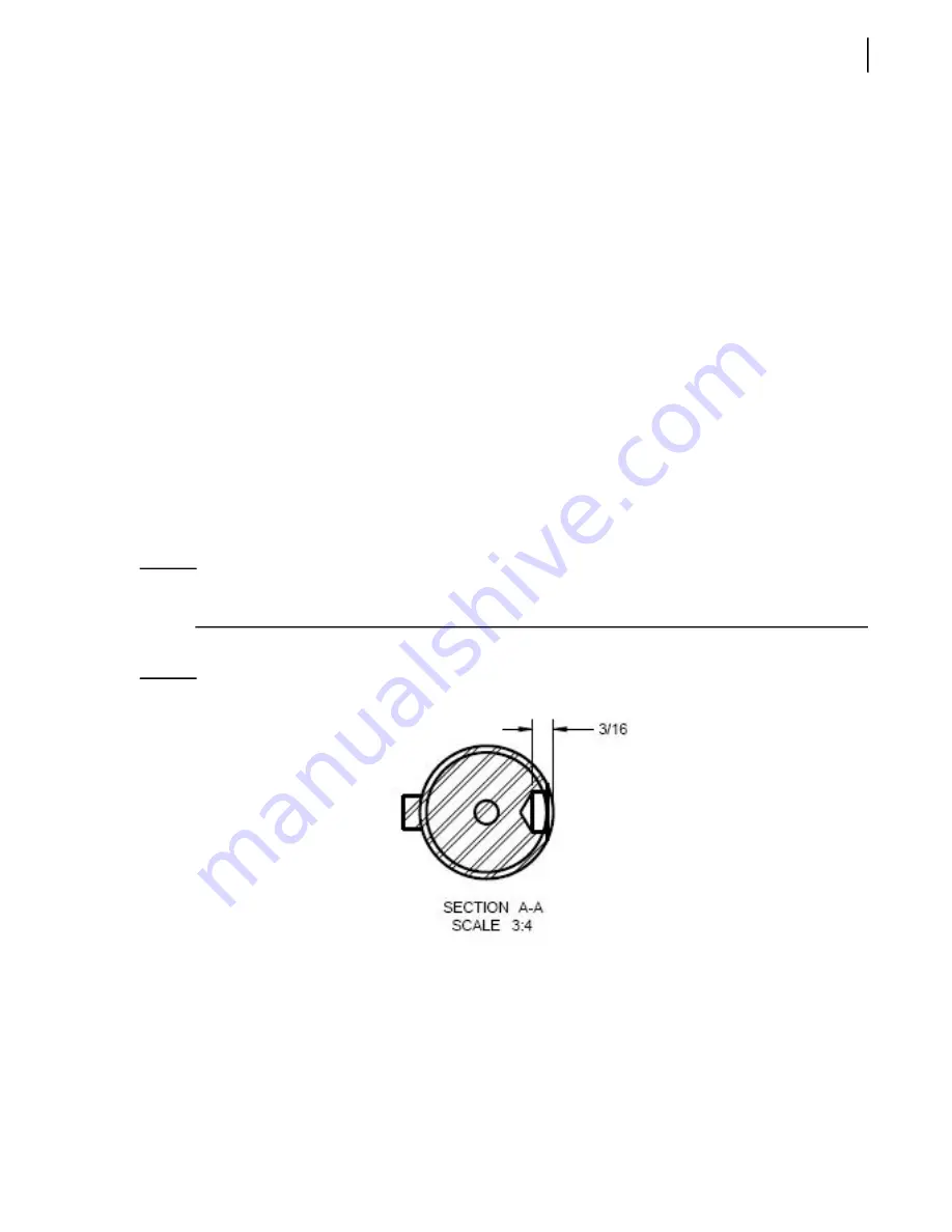
Drill a hole with a 5/16” diameter on the drive shaft.
Figure 5
-
13 Depth of hole to be drilled
13 c.
Reinstall the drive shaft.
13 d.
Place the yoke on the shaft as illustrated on page 125.
The yoke must be fully engaged on the shaft with both holes aligned (one hole over the
other).
13 e.
Apply Loctite 243 (medium strength) to bolt threads and insert the bolt firmly into the
holes to properly secure the yoke to the shaft.
Summary of Contents for AUTOMIZER FULL EJECT
Page 1: ...AUTOMIZERTM FULL EJECT MAINTENANCE MANUAL ...
Page 2: ......
Page 3: ...AUTOMIZERTM FULL EJECT MAINTENANCE MANUAL ...
Page 36: ...28 Safety ...
Page 112: ...104 Lubrication ...
Page 139: ...Hydraulic System 131 Figure 5 23 Strainer assembly Strainer ...
Page 144: ...136 Hydraulic System Figure 5 27 Detecting cylinder internal leaks 1 2 3 4 5 A A A ...
Page 160: ...152 Hydraulic System 0 1 2345 62789 ELECTRO HYDRAULIC VALVE HD RH ARM ...
Page 161: ...Hydraulic System 153 0 1 2345 62789 ELECTRO HYDRAULIC VALVE CRUSHER PANEL HD RH ARM ...
Page 164: ...156 Hydraulic System ...
Page 176: ...168 Electric System Cab Console Control Wiring ...
Page 177: ...Electric System 169 Control Box ...
Page 178: ...170 Electric System Chassis ...
Page 179: ...Electric System 171 Tailgate Lighting ...
Page 180: ...172 Electric System Left Body SideWiring ...
Page 181: ...Electric System 173 Right Body Side Wiring ...
Page 182: ...174 Electric System Camera s Switchpack s Layout Option s AUTO 10 SEC INHIBIT AUTO ...
Page 204: ...196 Troubleshooting ...
Page 205: ...Troubleshooting 197 ...
Page 206: ...198 Troubleshooting ...
Page 230: ...222 Multiplexing ...
Page 254: ...246 Lifting Arm Figure 10 27 Standard lifting arm ...
Page 255: ...Lifting Arm 247 ...
Page 256: ...248 Lifting Arm ...


