background image


Removing the rotor 

Using an adjustable or 1/4 inch wrench (some units are supplied with a wrench) 
loosen the screw and remove the rotor retaining screw/washer assembly by 
turning it counterclockwise. Lift the rotor directly upward in a straight vertical 
motion. 
Caution: Be sure to secure the rotor screw and tighten with a wrench before 
further operation. 

 
Overloading rotors 

The maximum load of the rotor and the maximum speed have been established 
by the manufacturer. Do not attempt to exceed these values. The maximum 
speed of the rotor has been measured for liquids having a homogeneous density 
of 1.2g/ml or less. In order to centrifuge liquids with a higher density it is 
necessary to reduce the speed. Failure to reduce the speed may result in 
damage to the rotor and centrifuge. The revised maximum speed can be 
calculated with the following formula:  
 
Reduced speed (n

red


     x max speed (n

max

 
Example: 
Where the density of the liquid is 1.7, the new maximum speed would be 
calculated as follows: 
 
n

red

 = 


x 14,000 = 9,882 rpm 

 
If in doubt concerning maximum speeds, please contact the manufacturer for 
assistance. 
 

Operation 

ATTENTION: Never attempt to operate the centrifuge with rotors or 
adapters that show signs of corrosion or mechanical damage. 
Never centrifuge strongly corrosive materials that may damage the 

rotors or accessories. 
 
Closing the lid 

After the rotor has been properly secured and loaded, close the centrifuge lid, 
making sure that the interlock has been engaged. 


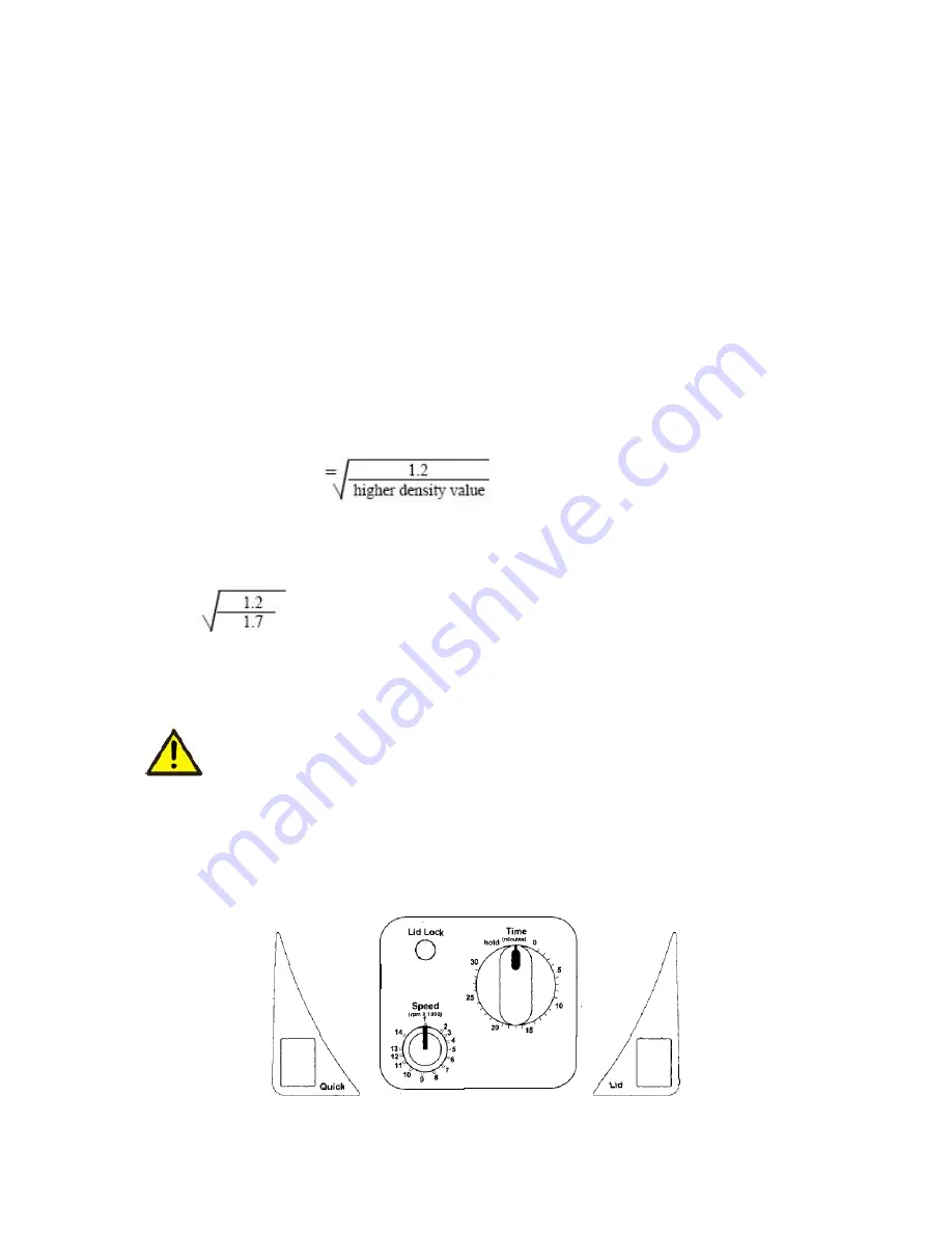
Figure 4. Spectrafuge 16M  Control panel layout 

Summary of Contents for Spectrafuge 16M

Page 1: ...Lit Code M00001 Rev 2 August 2016 Spectrafuge 16M Microcentrifuge User Manual C0160 C0160 100V C0160 230V...

Page 2: ...illage may harm unit NEVER put hands in the rotor area unless the rotor is completely stopped NEVER move the centrifuge while the rotor is spinning NEVER use solvents or flammables near this or other...

Page 3: ...tors and accessories Rotor maintenance Mounting and securing the angle rotors Removing the rotor Overloading rotors Operation 5 Closing the lid Lid release Lid lock Speed selection Selection of operat...

Page 4: ...mpaired Do not operate the centrifuge if any of the following conditions exist The centrifuge has not been installed properly The centrifuge is partially dismantled Service has been attempted by unaut...

Page 5: ...table laboratory bench cabinet etc To guarantee sufficient ventilation ensure that the centrifuge has at least 15cm 6 inches of free space on all sides including the rear The centrifuge should not be...

Page 6: ...ting and securing the angle rotor Remove the rotor screw from the motor shaft by turning the screw counterclockwise Clean the motor shaft and the rotor mounting hole see figures 1 2 Place the rotor on...

Page 7: ...4 Figure 1 Chamber and motor shaft Figure 2 Bottom of angle rotor Figure 3 Loading the rotor...

Page 8: ...igher density it is necessary to reduce the speed Failure to reduce the speed may result in damage to the rotor and centrifuge The revised maximum speed can be calculated with the following formula Re...

Page 9: ...labeled speed The scale is directly proportional to the speed a setting of 9 corresponds to 9 000rpm a setting of 13 corresponds to a speed of 13 000rpm etc Selection of operating time and momentary...

Page 10: ...The rotor should be cleaned after each use When spinning 8 samples containing phenol or phenol chloroform the rotor should be cleaned immediately after use Disinfection Should a spill of infectious ma...

Page 11: ...lose lid correctly Possible reason No speed or time has been selected Solution Set speed and or time Where to call Should you have any questions about the Spectrafuge 16M or its accessories please cal...

Page 12: ...l Force chart can be used to determine g values To use this chart find the radius value on the radius scale Place the edge of a ruler on the value Place the right side edge of the ruler on the speed s...

Page 13: ...s symbol identifies a Protective Earth PE terminal which is provided for connection of the supply system s protective earth green or green yellow conductor EQUIPMENT DISPOSAL EUROPEAN REGULATIONS Acco...

Page 14: ...paint or finish Claims for transit damage should be filed with the transportation carrier ALL WARRANTIES INCLUDING THE IMPLIED WARRANTY OF MERCHANTABILITY AND FITNESS FOR A PARTICULAR PURPOSE ARE LIMI...

Page 15: ...NOTES...

Page 16: ...9299560000 31 Mayfield Ave Edison NJ 08837 P 732 417 0700 F 732 417 1750 Toll Free 888 522 6381 labnetinfo corning com www labnetinternational com...

Reviews: