background image

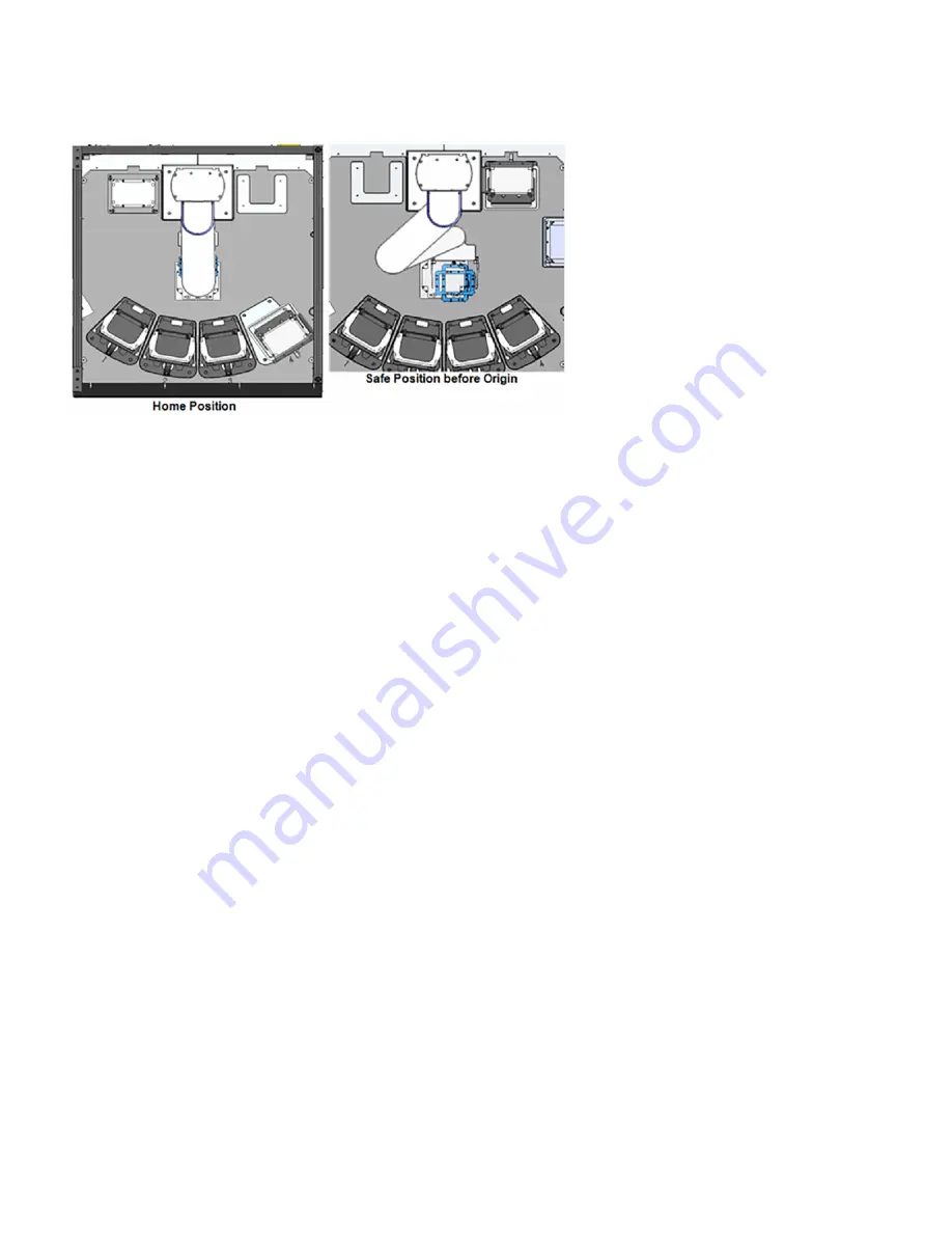
Figure 69: Move Robot/Gripper Arm To Safe Position

4. Make sure that all

ESTOP

buttons in the system are disengaged.

5. Return all components back to their locations and close all doors.
6. Reset the E-Stop safety relay by pressing the

Reset

button, which is located between the main

ESTOP

button and the

Run/Teach

key. This button changes to blue when it is active (in an E-Stop state).

7. Reinitialize all devices by clicking the

Initialize Devices

button on the Tempo Control Panel

Alarms

Tab.

8. Resolve error messages. There may be several error messages that result from pressing the

ESTOP

button or from the

original problem that required the emergency stop. The Possible Actions are:

a.

Reset errors and restart the job

- Clears any errors associated with the current job (scheduled task) and reissues

the job. You can use this to retry a scheduled action.

b.

Mark job as complete and continue

- Clears any errors associated with the current job, marks the job as completed,

and initiates the next scheduled action. You can use this to ignore an error and continue on with the remainder of a
protocol.

c.

Mark job as error and continue

- Saves error to the Run Time Errors LIst and intiates the next scheduled action. You

can use this to flag a specific job error for follow-up and continue with the remainder of the protocol.

d.

Mark job as error and stop

- Saves the error to the Run Time Errors List, archives all plates that are ot in their

original or final locations, and stops the protocol. You can resume the protocol from this point without editing (for
example, remapping plates, editing pick lists), and restarting.

e.

Mark job as error and abort

- Saves error to the Run Time Errors List, archives all plates that are not in their original

or final locations, and executes an emergency shutdown. You can resume the protocol from this point without
reinitializing the system, editing, and restarting.

70

PN | 001-15357

USER GUIDE | Access™ Dual Robot System

Recovering From An Emergency Shutdown

Summary of Contents for Access Dual Robot

Page 1: ...rsion 2 0 APRIL 2019 FOR RESEARCH USE ONLY LABCYTE INC 170 Rose Orchard Way San Jose CA 95134 USA Tel 1 408 747 2000 Email info us labcyte com USER GUIDE Access Dual Robot System 2019 LABCYTE INC All rights reserved MAN 2019 2 0 APRIL 2019 ...

Page 2: ...States and other countries All other registered or unregistered trademarks used herein are the exclusive property of their respective holders For research purposes only not for use in diagnostics Echo Liquid Handlers Applications Software and Automation Systems from Labcyte Inc are covered by one or more of the following patents United States 6 416 164 6 548 308 6 603 118 6 612 686 6 642 061 6 666...

Page 3: ...ional Safety Warnings 15 System Emergency Stop ESTOP Button 16 Light Tower System State Alerts 16 Alarm Alerts In Tempo 18 Interlock Sensors 19 Lid Presence Sensors 20 Teach Mode 20 4 System Requirements 21 Facility Requirements 21 Computer Specifications And Supported Operating System 21 Supported Software Versions 22 Supported Labware 22 5 System Dimensions 23 Safe System Configurations 23 Devic...

Page 4: ...ode To Online Mode 53 Transition The Echo Turntable From Online Mode To Standalone Mode 54 Troubleshooting 57 7 Basic Operations 59 Starting The Access System 59 Starting The Tempo Software 62 Initializing System Devices 63 Setting Up Before A Run 64 Shutting Down The Access System 66 Shutting Down The Software Only 67 Shutting Down For Maintenance Or Transport 67 Shutting Down By The Building Man...

Page 5: ...Access System Intended Audience The Access system is designed to be used by individuals who are familiar with good laboratory practices GLP 1 or a similar laboratory safety program Access system operators must read this guide before using the Access system Technical Support Resources For technical support issues support requests can be submitted via email to support labcyte com For telephone suppo...

Page 6: ...ho Dose Response User Guide l Echo Dose Response Quick Start Guide Document Conventions Style Purpose blue italicized text PDF Web only Cross references link Web addresses courier std Commands filenames directories paths user input bold text Interactive interface objects keys buttons italicized text Book titles glossary terms Safety Notation Marks This guide uses the following symbols in the left ...

Page 7: ...ion in the user guide associated with that instrument User guides for all instruments can be found on the installation CD l Compressed Air l Corrosive Chemicals l Crush Hazard l Cut Hazard l Earth Ground l Electrical Hazard l Eye Hazard l General Warning Label l Laser Hazard l Product Label l Tip Hazard l Trip Hazard Hazards are better indicated by hazard specific labels Clarion com or similar whe...

Page 8: ...Figure 2 Access System Product Safety Labels Locations 8 PN 001 15357 USER GUIDE Access Dual Robot System ...

Page 9: ...Figure 3 Access System Compressed Air Label Location Figure 4 Access System Laser Hazard Label Location CHAPTER 2 Product And Safety Labels 9 ...

Page 10: ...Figure 5 Access System Trip Hazard Label Locations Figure 6 Access System Product Label Location 10 PN 001 15357 USER GUIDE Access Dual Robot System ...

Page 11: ...odule s load lock doors A cut can occur if you do not keep your hands clear of the load lock doors while operating the machine 7 Crush Hazard This label is located in the space between a module and the robot frame A hand or foot can be crushed in that space when you push the button that triggers the motor to move the modules toward the robot frame 8 Electrical Hazard Underneath the Power Distribut...

Page 12: ...ponents Crush Hazard The Crush Hazard label indicates moving parts that can potentially injure the user Ensure parts are and will remain stationary before servicing Cut Hazard The Cut or Severe Hazard label warns the operator to keep their hands clear of this area while operating the system to prevent a possible cut injury Earth Ground The Earth Ground label indicates a grounding point in the syst...

Page 13: ...garded as Class 1 or Class 2 laser light hazards under normal operating conditions with instrument covers on Product Label The Access System Product label includes Labcyte corporate identification product identification product serial number regulatory agency marks origin of manufacture date of manufacture input power specifications WEEE symbol and the CE mark The Conformité Européenne CE Mark lab...

Page 14: ... module can be tipped over if someone is actively pushing on it Trip Hazard The Trip Hazard label draws attention to an obstacle or a change in elevation that presents the potential hazard 14 PN 001 15357 USER GUIDE Access Dual Robot System Tip Hazard ...

Page 15: ...ort see Technical Support Resources Note Refer to individual device user guides for user replaceable fuses l Do not use AC power cords if the following conditions exist as these conditions can cause an electrical shock hazard and result in severe injury l The power cords are frayed or damaged l Other attached cords cables or receptacles are frayed or damaged Using damaged power cords can cause an ...

Page 16: ...m State Alerts The Access system has four color Red Yellow Green Blue light towers that alert you to the state of the system Figure 9 Light Towers On The Access System This table describes the state of the Access system based on the light tower colors states Off On Blinking Note The BLUE light indicates that the robot is running in Slow Mode The two states that cause a robot to slow down are Any d...

Page 17: ...ctive but system is in a deadlock state Blinking Solid The user has not responded to errors from the Blinking Yellow state see above The Access system is in a deadlock state and awaiting action by the user A run is in progress the door to the storage module is unlocked There is a non blocking error on the system Blinking Blinking Indicates that a user action is required Blinking yellow indicates t...

Page 18: ...re shows the Alarms tab when there is an active Robot E Stop alarm Specific alarm instructions display and tell you how to recover from any alarm alert Figure 10 Alarm Tab Example Robot E Stop Alert Workcell Tab The Workcell Tab in Tempo indicates which door is open yellow icon on the system lets you turn the system lights on and off and provides module communication status 18 PN 001 15357 USER GU...

Page 19: ...e location and the type of sensor All sensor events are logged and communicated through Tempo software Alarms Tab and the integrated light tower system alerts This table lists operator actions that trigger a sensor and how that impacts the Access system Actions That Trigger Sensors Impact on the Access System Device door is opened l Robots are slowed into safety mode Device shelf is pulled l Robot...

Page 20: ...t plates at devices can finish but no new work can begin Module is pulled back from the Access system while the cables are attached l Robot is stopped l Echo is paused if the module is an Echo module otherwise the module is running normally l All devices on the undocked module are switched to Standalone mode l Run in progress continues but because the robot is E stopped only current plates at devi...

Page 21: ...ocking capabilities To meet docking repeatability specifications the floor levelness must fall within the range of the following specifications and standards l ASTM E 1155 Standard l FF35 FL25 to FF50 FL30 Laboratory Environment Requirement l Ambient temperature 21 C 2 C relative humidity 10 80 non condensing Facilities HVAC input requirements for low RH option l Temperature 20 C 1 C relative humi...

Page 22: ...ftware 7 0 or greater using Titian s Tempo Fulfillment Module Supported Labware Supported labware includes l All Echo qualified microplates acoustic tubes and most ANSI compliant SLAS standard microplates in 96 384 1536 and 3456 well formats 8 to 16 mm total height without lid l Total height including lids l 25 Position Random Access Plate Hotels Max Labware Height allowed including lids 15 9mm l ...

Page 23: ...torage Module Safe System Configurations The Access DRS can be configured with or without devices or modules If a module is removed the system can still continue operation if the following conditions are met l Any device which is removed is not used in the protocol for the run that is in progress l The surrounding enclosure for a device is in place l Any device which is removed and does not have a...

Page 24: ...eler peeler centrifuge and PlateLoc Figure 12 Device Module 1 Right Front View Callout Number Device Name 1 Agilent Microplate Labeler VCode 2 Brooks XPeel 3 BioNex HiG3 Centrifuge 4 Agilent PlateLoc Table 5 Callout table for Device Module 1 Right Front View 24 PN 001 15357 USER GUIDE Access Dual Robot System Device Module 1 ...

Page 25: ...Figure 13 Device Module 1 Right Top View Device Module 1 CHAPTER 5 System Dimensions 25 ...

Page 26: ... devices including a nest centrifuge and the PlateLoc Figure 14 Device Module 2 Right Front View Callout Number Device Name 1 Certus Nest 2 Agilent PlateLoc 3 BioNex HiG3 Centrifuge Table 6 Callout Table for Device Module 2 Front View 26 PN 001 15357 USER GUIDE Access Dual Robot System Device Module 2 ...

Page 27: ...Figure 15 Device Module 2 Top View Device Module 2 CHAPTER 5 System Dimensions 27 ...

Page 28: ...s a front and top view of the Echo module Figure 16 Echo Module Front View Callout Number Name 1 Echo Nest 2 IntelliXcap Table 7 Callout table for Echo Module Front View 28 PN 001 15357 USER GUIDE Access Dual Robot System Echo Module ...

Page 29: ...Figure 17 Echo Module Top View Echo Module CHAPTER 5 System Dimensions 29 ...

Page 30: ...Storage Module This section provides a front and top view of the AmbiStore storage module Figure 18 Storage Module AmbiStore Front View 30 PN 001 15357 USER GUIDE Access Dual Robot System AmbiStore Storage Module ...

Page 31: ...Figure 19 Storage Module AmbiStore Top View AmbiStore Storage Module CHAPTER 5 System Dimensions 31 ...

Page 32: ...torage Module This section provides a back and top view of the MicroServe storage module Figure 20 Storage Module MicroServe Front View 32 PN 001 15357 USER GUIDE Access Dual Robot System MicroServe Storage Module ...

Page 33: ...Figure 21 Storage Module MicroServe Top View MicroServe Storage Module CHAPTER 5 System Dimensions 33 ...

Page 34: ...t Storage Module This section provides a front and top view of the Cytomat storage module Figure 22 Storage Module Cytomat Side View 34 PN 001 15357 USER GUIDE Access Dual Robot System Cytomat Storage Module ...

Page 35: ...Figure 23 Storage Module Cytomat Top View Cytomat Storage Module CHAPTER 5 System Dimensions 35 ...

Page 36: ...Robot Cell Figure 24 Robot Cell Front View Figure 25 Robot Cell Top View 36 PN 001 15357 USER GUIDE Access Dual Robot System Robot Cell ...

Page 37: ...n until it needs to access the storage device At that point it pauses and waits for you to close the storage module door and lock it before resuming operation LOCK If the storage device is unlocked and Offline Unlock button was pressed close the storage module door and press the LOCK button so the device can resume operation ESTOP In an emergency press the ESTOP button to disable motor power to th...

Page 38: ...guide the module up against the Access system and hold the module in the docked position until the audible alarm stops and the UNDOCKED light turns on ESTOP In an emergency press the ESTOP button to disable motor power to the robot air power throughout the system and any integrated devices that provide support for the E Stop connection such as an Echo liquid handler It also terminates any currentl...

Page 39: ...and lock storage devices perform an emergency stop reset the system after an emergency stop and select the system Run or Teach mode 3 System Control Panel buttons without Reset or operation mode Unlock and lock storage devices and perform an emergency stop Table 10 Callout table forControl Panel Buttons Location On Access System Main Disconnect Switch The Main Disconnect Switch allows you to turn ...

Page 40: ...latches Note when you open a device module door with safety sensors the robot slows down with the protocol still operating Doors with no latches require an 8mm hex key tool to open them and the robot still operates at full speed Examples of panels or doors that require tool entry include the l Lower side panels of a module l Large panel between the robot and the Echo module l Large side panels of ...

Page 41: ...a robot accessible position l If a run is scheduled while a shelf is extended the run does not start l If a run is in progress the robot does not attempt to move a plate to the device until the shelf holding the device is retracted If a robot move to a device on the shelf is in progress and the shelf gets extended the robot attemps to place the plate since the move had already been scheduled Labcy...

Page 42: ...igure 33 Device Shelf Extended On Echo Module Figure 34 Correct Method Of Sliding A Device Shelf With Waste Bottle Underneath 42 PN 001 15357 USER GUIDE Access Dual Robot System Operating Device Shelves ...

Page 43: ...powered You can undock a device module mid run to access the inside of the robot cell and then redock the module and reinitialize the system To complete a temporary undock do this 1 Pause the Tempo protocol that is currently running 2 Locate the UNDOCK button on the module you want to undock 3 Press and hold the UNDOCK button until the audible alarm stops and the DOCK button turns on An alarm soun...

Page 44: ...a system reset and a blanking panel for continued use To fully undock a module do this Note All protocols in progress are aborted and cannot be continued after an E Stop is triggered 1 Locate the UNDOCK button on the module you want to undock 2 Press and hold the UNDOCK button until the audible alarm stops and the DOCK button turns on An alarm sounds and the UNDOCK button light turns off when the ...

Page 45: ...ou are not redocking the module a Attach a blanking panel in the space where the module was located This panel needs to be the same size as the door or panel from the device or Echo module that is being removed b Place the panel in the space where the module was located c To keep cables off the ground hook them on the hanger Docking And Undocking Device Modules CHAPTER 6 Interacting With The Acces...

Page 46: ... RESET button located on the Access system Control Panel e Reinitialize the Access system to continue using the system 6 Remove the rear HVAC input to the Echo by lifting the coupling assembly straight up and out 46 PN 001 15357 USER GUIDE Access Dual Robot System Docking And Undocking Device Modules ...

Page 47: ... Access system Control Panel d Reinitialize the Access system to continue using the system Removing Fixed Storage Modules To perform maintenance on a storage device that is located in a storage module you need to first remove the storage module manually from the robot cell You may be need to remove it using the manual latches Pull the latch to unlatch the module from the robot cell push the latch ...

Page 48: ...ss the storage device At that point it pauses and waits for the you to close and lock the door before resuming Actuating doors between the storage devices and the robot cell close The system remains in operation but does not attempt to access the Offline storage device 2 Manually unlock the three storage module latches and open the door 3 Rotate the storage device freely to load and unload plates ...

Page 49: ...Figure 45 AmbiStore Fixed Storage Module Loading And Unloading Labware CHAPTER 6 Interacting With The Access System 49 ...

Page 50: ...The Echo Turntable is a rotating mount that provides easy access to the Echo and allows for Standalone use when the Echo is not being used in a Tempo protocol The Echo Turntable can be rotated up to 180 can be locked every 45 and has a safety door Tunnel door that allows the Access robot to move plates to and from Echo stages This table describes the Echo modes available in the Tempo software Echo...

Page 51: ... position or mode it is user accessible outside of Tempo and is driven by Echo applications directly To move the Echo Turntable from Online to a Standalone position The latch is locked when it is in the horizontal home position There is a sensor a the home position to detect orientation 1 To unlock the Echo Turntable rotate the turntable latch until it disengages to release and unlock the turntabl...

Page 52: ...e turntable so that the latch locks into a groove You may need to slightly rotate it to ensure the latch falls into place Once the latch is locked you can use the Echo in Standalone mode and the Echo cannot be moved To move the Echo Turntable from Standalone to an Online position 1 Unlock the Echo Turntable See Step 1 2 Rotate the Echo back to the Home Robot accessible position See Step 2 3 Make s...

Page 53: ...llout Number Name Description 1 Tunnel door Tunnel door is open when transitioning the Echo from Standalone to Online Table 15 Callout table for Turntable Tunnel Door 3 When the Tempo Safety dialog box shown below appears click Reset Safety Relays 4 Verify the Echo Liquid Handler is online in Tempo by navigating to the Hardware tab Select Echo and then Online from the drop down menu if it is not a...

Page 54: ...verification that the Echo is not in use If the Echo is already Offline you can move forward with transitioning to Standalone mode Figure 50 Echo Online Mode 2 If you attempt to change the mode to Offline while an active run is in process Tempo displays a dialog box that informs you that the device mode cannot be changed while an active run is in process Figure 51 Runs In Progress Dialog Box 3 If ...

Page 55: ...ote that other protocols that do not use the Echo can run on the Access system You can also view the Echo turntable sensor status by clicking on the Module Status button 6 If the Echo Turntable is committed to an active protocol run the transition to Standalone mode the Standalone Mode Event Echo dialog box displays Using The Echo Turntable For Standalone Use CHAPTER 6 Interacting With The Access ...

Page 56: ...anual transition to or from Standalone mode is not allowed during a protocol run The same applies to Online and Offline modes which are also not allowed to be changed during a protocol run 8 Close the Tunnel door 9 Verify that the Echo Turntable Standalone position and Tunnel door Closed mode are as shown below 10 Verify that the Echo Turntable is in Standalone mode by checking the device status i...

Page 57: ...ot fully open To fix this error go to the Echo and open the Tunnel door completely Figure 55 Echo Error Tunnel Door Not Open The following figure shows an error when Tempo software attempts to run a protocol when the physical Echo mode is set to Standalone To fix this error you need to physically transition the Echo Turntable from Standalone mode to the Online mode Home position Figure 56 Echo Err...

Page 58: ...USER GUIDE Access Dual Robot System Using The Echo Turntable For Standalone Use 58 PN 001 15357 This page was intentionally left blank ...

Page 59: ...n is solid blue f Teach key is turned to Run Mode 2 Turn on each device Refer the specific device user guide for instructions 3 Launch Tempo software and navigate to Control Panel Alarms to view the state of the Access system The Safety System Resources and Environment alarms need to be green indicating that the system is in an idle state and ready to start normally The Run Mode alarm needs to be ...

Page 60: ...tatus 4 If the Door Relay alarm is yellow click Workcell tab to view which doors are open Closed door indicators are green and open door indicators are yellow 60 PN 001 15357 USER GUIDE Access Dual Robot System Starting The Access System ...

Page 61: ...system enclosure Figure 58 Workcell Tab Open Door Indicators 6 After you determine the Access system is idle and all doors are closed Click the Initialize Devicesbutton on the Alarms tab Starting The Access System CHAPTER 7 Basic Operations 61 ...

Page 62: ...grams Labcyte Tempo Tempo Software b Select the Tempo application Figure 59 Directory Location of the Tempo Software Note To create a shortcut to Tempo Software on the conputer desktop right click on Tempo Software icon and select Send to then Desktop 62 PN 001 15357 USER GUIDE Access Dual Robot System Starting The Tempo Software ...

Page 63: ...ar icon to display a drop down menu 2 Click Initialize to display the Tempo System Initialization screen Figure 60 File System Commands 3 Ensure that all the devices are selected in the Initialize column of the Tempo System Initialization screen and click Start Initializing System Devices CHAPTER 7 Basic Operations 63 ...

Page 64: ...need to clear the plate locations a Open the Tempo software click the Plates tab and select a storage device Plate locations are listed for each rack b Select the plate locations or rack you want to clear Click Empty Selected Locations or Empty Selected Racks to clear plate information from the software 3 Load one or more racks with source and destination plate as well as any additional plates you...

Page 65: ...hat the matching sealer insert is in the plate sealer 8 Check for lids and plates from a previous run in the delidder rack and temporary storage rack 9 Check the temperature of the Echo coupling fluid on the control panel It should read 22 C 10 Check the fluid level in the coupling fluid bottle at the back of the Echo instrument 11 Ensure all safety doors are closed You can check if all doors are ...

Page 66: ...is being started after a transport or extended down time check with a Labcyte representative for more information Unplanned Shutdown l Shut down by the Building Management System BMS If the Access system receives a signal from the BMS to shut down the system stops all runs in progress and runs in the scheduler queue Once all runs in progress are stopped and archived and the system is idle Tempo au...

Page 67: ...hat no new runs start Let all runs finish so they can be archived to their final location 2 Click File or the Gear icon to display the System Menu 3 Click Shutdown to exit the software and shut down the computer This initiates a controlled shutdown of the Access system which shuts down the Echo instruments and powers off the Tempo controller The following alert displays Figure 65 Shutdown Confirma...

Page 68: ...lays alarm alerts when power and environmental problems occur Shutting Down In An Emergency To shut down in an emergency 1 To stop a run immediately in the case of emergency completely press the red ESTOP button The ESTOP button can be used in an emergency to stop robot motion and activity of all devices immediately with the exception of the computer The position of the robot or the state of the o...

Page 69: ... red indicating that all operations have stopped Follow the steps in the E Stop Alarm Instructions screen for recovery as they may be customized for your site Figure 68 E Stop Tab Access System E Stop Alarm Instructions To recover from an emergency stop 1 Resolve any unsafe condition that caused the ESTOP button to be pressed 2 Open the deck door and manually clear any plates or other obstructions...

Page 70: ...e Clears any errors associated with the current job marks the job as completed and initiates the next scheduled action You can use this to ignore an error and continue on with the remainder of a protocol c Mark job as error and continue Saves error to the Run Time Errors LIst and intiates the next scheduled action You can use this to flag a specific job error for follow up and continue with the re...

Page 71: ...Figure 70 Sample Error Screen Robot Device Recovering From An Emergency Shutdown CHAPTER 7 Basic Operations 71 ...

Page 72: ...USER GUIDE Access Dual Robot System Recovering From An Emergency Shutdown 72 PN 001 15357 This page was intentionally left blank ...

Page 73: ...e contract Maintenance procedures are explained in these sections l Weekly Maintenance l Yearly Maintenance Weekly Maintenance Every week users need to complete the following maintenance tasks l Check The Gaskets l Inspect The Locating Features l Change The Echo Coupling Fluid l Check The Suction Cups l Purge The Water Vapor Check The Gaskets To check gaskets 1 First undock and dock each module to...

Page 74: ...s for scratches or wear 2 Apply a thin coat of GPL 207 lubricant to the locating ramps Figure 72 Apply Lubricant To Ramps Change The Echo Coupling Fluid For instructions refer to the Echo 650 Series Liquid Handler User Guide 74 PN 001 15357 USER GUIDE Access Dual Robot System Weekly Maintenance ...

Page 75: ...ce For systems under service contract or warranty Labcyte conducts an annual product maintenance PM The annual PM covers the following items l Grease all moving interference components docking lead screw and bearings l Inspect moving parts casters pivot points and bearings l Inspect stackers l Inspect electrical components l Conduct an Echo product maintenance procedure l Clean and back up the Tem...

Page 76: ...ccess are registered trademarks or trademarks of Labcyte Inc in the U S and or other countries LABCYTE INC 170 Rose Orchard Way San Jose CA 95134 USA Toll free 1 877 742 6548 Fax 1 408 747 2010 SUPPORT North America Europe Japan Asia Other 1 408 747 2000 44 1543 276543 81 03 5530 8964 61 39018 5780 1 408 747 2000 support labcyte com support labcyte com japan labcyte com asiapacific labcyte com sup...

Reviews: