


Pennant Pool Heater
Page 7
(5.5 square cm/kW) of total input rating of all
equipment in the enclosure. When communicating to
the outdoors through horizontal ducts, each opening
shall have a minimum free area of not less than
1 square inch per 2000 Btu/hr (11 square cm/kW) of
total input rating of all equipment in the enclosure.
Table 3 shows data for this sizing method, for each
Pennant model.
Method 2
: One permanent opening, commencing
within 12 inches (30 cm) of the top of the enclosure,
shall be permitted. The opening shall directly
communicate with the outdoors or shall communicate
through a vertical or horizontal duct to the outdoors or
spaces that directly communicate with the outdoors
and shall have a minimum free area of 1 square inch
per 3000 Btu/hr (7 square cm/kW) of the total input
rating of all equipment located in the enclosure. This
opening must not be less than the sum of the areas of
all vent connectors in the confined space.
Other methods of introducing combustion and
ventilation air are acceptable, providing they conform
to the requirements in the applicable codes listed
above.
In Canada, consult local building and safety
codes or, in absence of such requirements, follow
CAN/CGA B149.
2.1.2 Intake Combustion Air
Never obtain combustion air from the pool area.
Corrosion of and/or damage to the pool heater may
result. The combustion air can be taken through the
wall, or through the roof. When taken from the wall, it
must be taken from out-of-doors by means of the
Laars horizontal wall terminal (see Table 2). When
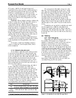
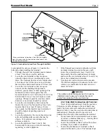
taken from the roof, a field-supplied rain cap or an
elbow arrangement must be used to prevent entry of
rain water (see Figure 2).
Use single-wall galvanized pipe, per table 4,
for the combustion air intake (see Table 1 for
appropriate size). Route the intake to the heater as
directly as possible. Seal all joints with tape. Provide
adequate hangers. The unit must not support the
weight of the combustion air intake pipe. Maximum
linear pipe length allowed is 50 feet (15.2m). Three
elbows have been calculated into the 50-foot (15.2m)
linear run. Subtract 10 allowable linear feet (3.0m) for
every additional elbow used (see Table 1). When
fewer than 3 elbows are used, the maximum linear
pipe length allowed is still 50 feet (15.2m).
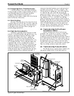
The connection for the intake air pipe is on the
filter box. The Pennant appliances may have venting
and combustion air ducting attached to the top or the
back. They are shipped with the connections at the
top. For attaching either or both pipes to the back, the
mounting flanges are reversible by removing the
mounting screws and orienting the flanges in the
desired position. Replace the screws after positioning
flanges. Run a bead of silicone around the collar and
slide the pipe over the collar. Secure with sheet metal
screws.
In addition to air needed for combustion, air shall
also be supplied for ventilation, including all air
required for comfort and proper working conditions
for personnel. The Pennant loses less than 1 percent of
its input rating to the room, but other heat sources may
be present.
2.2 Venting
2.2.1 Vent Categories
Depending upon desired Pennant venting, it may
be considered a Category I or a Category III
appliance. In general, a vertical vent system will be a
Category I system. However, in rare instances, a
Pennant’s vertical vent system may be considered
Category III. In the U.S., the National Fuel Gas Code
(American National Standard Z223.1-Latest Edition),
or in Canada the CSA B149.1 (latest edition), defines
a Category I vent system, and includes rules and tables
to size these vent systems. If the Pennant’s vertical
vent system does not satisfy the criteria for Category I
venting, it must be vented as a Category III system.
All Pennant vent systems which discharge
horizontally (without the use of a power venter) are
considered Category III vent systems.
Figure 2. Combustion Air and Vent Through Roof.
TERM
DESCRIPTION
Pipe
Single-wall galvanized steel pipe, 24 gauge
minimum (either insulated or non-insulated)
Joint
Permanent duct tape or aluminum tape
Sealing
Table 4. Required Combustion Air Piping Material.
Summary of Contents for Pennant PNCP 1000
Page 28: ...LAARS Heating Systems Page 28 Figure 9 Sheet Metal Components...
Page 29: ...Pennant Pool Heater Page 29 Figure 10 Internal Components...
Page 32: ...LAARS Heating Systems Page 32 Figure 13 Pennant 1250 2000 Ladder Diagram...
Page 33: ...Pennant Pool Heater Page 33 Figure 14 Pennant 500 1000 Wiring Schematic...
Page 34: ...LAARS Heating Systems Page 34 Figure 15 Pennant 1250 2000 Wiring Schematic...
Page 35: ...Pennant Pool Heater Page 35 Figure 16 Field Wiring PNCP 500 1000...


