Mini-Therm II Hydronic Boiler
Page 5
Distance
From Gas
Meter
Boiler Size
50
75
100
125
160
225
Pipe Size
0-50'
1/2
3/4
3/4
3/4
1
1
0-15m
50-100'
3/4
3/4
3/4
1
1
1-1/4
15-30m
100-200'
3/4
1
1
1
1-1/4
1-1/4
30-60m
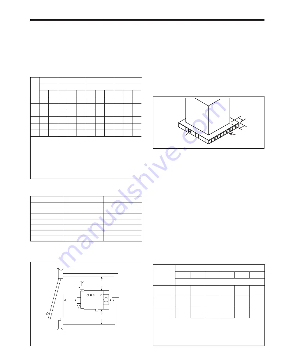
Figure 2. Closet and Alcove Installation (see Table 3).
consisting entirely of a combination of steel, iron,
brick, tile, concrete, slate, glass or plaster.
All boilers can be installed on a combustible
floor if a non-combustible base assembly, available
from Laars, is used. See the boiler rating plate for the
appropriate base part number. Boilers must never be
installed on carpeting.
As an alternative to the Laars non-combustible
base plate, the National Fuel Code allows a boiler to
be placed on other than a non-combustible surface
when such an installation complies with the American
Insurance Code. This code specifies the surface under
the boiler be protected with hollow masonry no less
than 4" (102mm) thick, covered with sheet metal at
least 24 ga. in thickness. Such masonry must be laid
with ends unsealed, and joints matched in such a way
as to provide a free circulation of air from side to side
through the masonry (see Figure 3).
Dimensions in inches (mm).
1F. Gas Supply and Piping
Review the following instructions before
proceeding with the installation.
1.
Verify that the boiler is fitted for the proper
type of gas by checking the rating plate. Laars
boilers are normally equipped
to operate below a 2000 foot altitude. Boilers
equipped to operate at higher altitudes have
appropriate stickers or tags attached (next to the
rating plate).
2.
Use the figures in Table 4 to provide adequate
gas piping from the gas meter to the boiler.
3.
A trap (drip leg) must be provided ahead of the
gas controls (see Figure 4). A manual gas shutoff
valve must also be provided for service
convenience and safety. Check the local codes.
Table 3. Minimum Boiler Clearances
From Combustible Surfaces.
Table 4. Gas Piping Sizes.
Size
1/2" Pipe
3/4" Pipe
1" Pipe
1-1/4" Pipe
Pump H.P.
Pump H.P.
Pump H.P.
Pump H.P.
1/25 1/12 1/25 1/12 1/6 1/25 1/12 1/6 1/25 1/12 1/6
50
50
99
390 680
*
*
*
*
*
*
*
75
*
35
160 300 460 640
*
*
*
*
*
100
*
*
77
150 260 330 620
*
*
*
*
125
*
*
27
80
140 170 360 600
*
*
*
160
*
*
*
25
72
57
160 330 190 480
*
225
*
*
*
*
*
*
*
110
*
69
330
*A circular and/or primary/secondary piping are required. Consult
factory.
1. Chart is based on 30°F (-1°C) maximum temperature rise.
2. Calculations are based on Type L copper tubing with one
zone valve and eight elbows.
3. Typical circulating pumps:
1
/
25
HP=Taco 007, B&G LR-20 or
SLC-25, Grundfos UP15-42F, or equivalent.
1
/
12
HP=B&G LR-
12, Grundfos UP26-42F, or equivalent.
1
/
6
HP=B&G series
HV, Grundfos UP43-75, or equivalent.
Table 2. Maximum Suggested Circuit Length in Feet.
Note: These figures are for Natural Gas (.65 Sp. Gr.), and are
based on 1/2" water column pressure drop. Check supply
pressure with a manometer, and local code requirements for
variations. For LPG, reduce pipe diameter one size, but
maintain a 1/2" minimum diameter. A 'normal' number of Tees
and elbows have been taken into allowance.
Figure 3. Typical Combustible Floor Installation.
Sheet Metal Cover
Min. Thickness 24 Gauge
Galvanized
Hollow
Concrete
Block
12"
Min.
Sheet Metal Cover
Min. Thickness 24
Gauge Galvanized
Hollow
Concrete
Block
12" Min.
(305mm)
6 (152)
6 (152)
6 (152)
4*
(102)
*6" for models JV160 to JV225.
Boiler Sizes
50-125
160-225
Clearances
in
mm
in
mm
Left side
6
152
6
152
Right side
6
152
6
152
Rear
6
152
6
152
Front
4
102
6
152
Flue
6
152
6
152
Top
23
484
36
914


